Gmc Sierra Tail Light Wiring Diagram
Understanding the tail light wiring diagram for your GMC Sierra is crucial for anyone looking to perform repairs, upgrades, or modifications to their vehicle's lighting system. A solid grasp of this diagram can save you time, money, and potential headaches by allowing you to diagnose and resolve electrical issues efficiently and safely. This article will provide a comprehensive breakdown of the Sierra tail light wiring diagram, covering its purpose, key components, and practical applications.
Purpose of the GMC Sierra Tail Light Wiring Diagram
The tail light wiring diagram is essentially a roadmap for the electrical circuits that power your Sierra's tail lights. It illustrates the connections between various components, including the light bulbs, sockets, wiring harnesses, fuses, relays, and the vehicle's control modules. The diagram serves several essential purposes:
- Troubleshooting Electrical Issues: When a tail light stops working, the diagram helps you trace the circuit, identify potential points of failure (e.g., blown fuse, broken wire, faulty bulb), and pinpoint the source of the problem.
- Performing Repairs: Whether you're replacing a damaged wire, installing a new tail light assembly, or fixing a faulty connector, the diagram provides the necessary information to ensure proper connections.
- Making Modifications and Upgrades: If you're adding aftermarket lighting accessories, such as LED tail lights, sequential turn signals, or trailer wiring, the diagram helps you tap into the correct circuits and avoid damaging the vehicle's electrical system.
- Understanding the System: Even if you're not currently experiencing any issues, studying the diagram can enhance your understanding of how the tail light system functions, enabling you to perform preventive maintenance and anticipate potential problems.
Key Specs and Main Parts of the Tail Light System
Before diving into the specifics of the wiring diagram, it's important to familiarize yourself with the key components of the GMC Sierra's tail light system:
- Tail Light Assembly: This houses the various light bulbs, reflectors, and lenses that make up the tail light system. It typically includes brake lights, tail lights (running lights), turn signals, and backup lights.
- Light Bulbs: These are the light-emitting devices. Different types of bulbs are used for different functions (e.g., incandescent, halogen, LED). Each has specific wattage and voltage requirements.
- Sockets: These provide the electrical connection to the bulbs and hold them securely in place.
- Wiring Harness: This is a bundle of wires that connect the various components of the tail light system to the vehicle's electrical system. Each wire is typically color-coded for easy identification.
- Fuses: These are safety devices that protect the electrical circuits from overcurrent. If a circuit draws too much current, the fuse will blow, interrupting the circuit and preventing damage to other components. The amperage rating is critical and should never be substituted for a higher rating without careful consideration.
- Relays: These are electromechanical switches that control high-current circuits using a low-current signal. They are commonly used in lighting systems to control the flow of power to the lights.
- Control Modules: Modern vehicles often use electronic control modules (ECMs) or body control modules (BCMs) to manage the lighting system. These modules receive inputs from various sensors and switches and control the output to the tail lights.
- Ground Points: These are connection points where the electrical circuit is grounded to the vehicle's chassis. A good ground connection is essential for proper operation of the electrical system.
Understanding the Symbols in the Wiring Diagram
Wiring diagrams use standardized symbols to represent electrical components and connections. Here's a breakdown of some common symbols you'll encounter in a GMC Sierra tail light wiring diagram:
- Lines: Lines represent wires. Solid lines indicate a direct connection, while dashed lines may represent a shielded wire or a connection through a connector. Line thickness might indicate wire gauge (thicker lines = larger gauge).
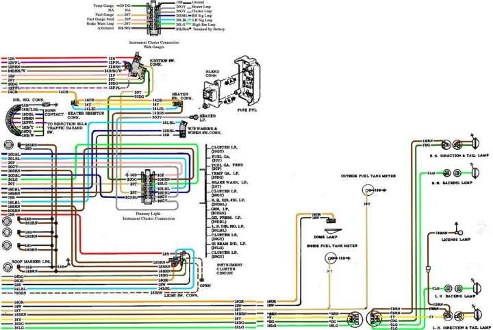
- Colors: Each wire is typically color-coded to help identify its function. Common colors include black (ground), red (power), yellow (turn signal), and brown (tail lights). The diagram will usually include a color code chart.
- Circles: Circles can represent light bulbs or other components. Often, the component name or abbreviation is inside the circle.
- Squares/Rectangles: These typically represent components like relays, fuses, or control modules.
- Zigzag Line: This usually represents a resistor.
- Ground Symbol: A symbol resembling an upside-down tree represents a ground connection.
- Connectors: Connectors are represented by various symbols depending on the type of connector. Often shown as interlocking shapes.
It's crucial to consult the specific wiring diagram for your GMC Sierra model year, as symbols and color codes can vary. The diagram will typically include a legend that explains the meaning of each symbol and color.
How the Tail Light System Works
The GMC Sierra tail light system operates on a simple principle: when a switch is activated (e.g., the headlight switch, brake pedal, turn signal stalk), it sends an electrical signal to the appropriate components, causing the corresponding lights to illuminate. Let's examine the basic operation of each function:
- Tail Lights (Running Lights): When the headlight switch is turned to the "on" or "parking light" position, it sends power to the tail light circuit. This power flows through a fuse, a relay (if equipped), and the wiring harness to the tail light bulbs, causing them to illuminate.
- Brake Lights: When the brake pedal is pressed, it activates a brake light switch. This switch sends power to the brake light circuit, bypassing the tail light circuit. This causes the brake lights to illuminate brighter than the tail lights, indicating that the vehicle is braking.
- Turn Signals: When the turn signal stalk is activated, it sends a signal to the turn signal flasher. The flasher interrupts the power to the turn signal circuit, causing the turn signal lights to blink on and off. A separate bulb is used for each side.
- Backup Lights: When the vehicle is shifted into reverse, the backup light switch is activated. This switch sends power to the backup light circuit, causing the backup lights to illuminate, providing illumination behind the vehicle.
In modern vehicles, the BCM plays a crucial role in managing the tail light system. It receives inputs from various sensors and switches and controls the output to the tail lights. This allows for features such as automatic headlight control, trailer light control, and bulb outage detection.
Real-World Use: Basic Troubleshooting Tips
Here are some basic troubleshooting tips for common tail light issues:
- No Tail Lights: Check the tail light fuse first. If the fuse is blown, replace it with a fuse of the same amperage rating. If the fuse blows again immediately, there's likely a short circuit in the system.
- One Tail Light Out: Check the bulb first. If the bulb is good, check the socket for corrosion or damage. Use a multimeter to check for voltage at the socket when the tail lights are supposed to be on.
- Brake Lights Not Working: Check the brake light fuse and the brake light switch. The switch is typically located near the brake pedal.
- Turn Signals Not Working: Check the turn signal fuse and the flasher unit. A rapid flashing indicates a bulb is likely out.
- Dim or Flickering Lights: Check the ground connections. A poor ground connection can cause dim or flickering lights.
Safety Precautions
Working with automotive electrical systems can be dangerous. Here are some important safety precautions to keep in mind:
- Disconnect the Battery: Always disconnect the negative terminal of the battery before working on any electrical components. This will prevent accidental short circuits and electrical shocks.
- Use Proper Tools: Use insulated tools to prevent electrical shocks.
- Refer to the Wiring Diagram: Always refer to the wiring diagram to ensure proper connections.
- Be Careful with Fuses: Never replace a fuse with a fuse of a higher amperage rating. This can overload the circuit and cause a fire.
- High-Intensity Bulbs/LEDs Many modern vehicles use complex CAN-BUS systems. Incorrectly installed or incompatible LED replacements can cause system errors or even damage the vehicle's electronics. Consult with a professional when upgrading to aftermarket LED lighting.
Working on the tail light system can expose you to risks such as electrical shock. If you are not comfortable working with electrical systems, it's best to consult a qualified mechanic.
We have a detailed GMC Sierra tail light wiring diagram file available for download. This diagram will provide you with a visual representation of the circuits and components involved in your vehicle's tail light system.