Gmc Truck Pinout Gm Instrument Cluster Wiring Diagram
Understanding the GMC truck pinout and GM instrument cluster wiring diagram is crucial for a variety of tasks, from diagnosing electrical issues and performing repairs to customizing your vehicle with aftermarket components. This document serves as your guide to deciphering these diagrams, providing you with the knowledge to confidently tackle automotive electrical projects.
Purpose of the Instrument Cluster Wiring Diagram
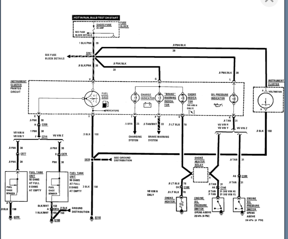
The instrument cluster wiring diagram is essentially a roadmap of the electrical system that powers and controls the gauges, indicators, and warning lights within your GMC truck's instrument panel. It details the specific wiring connections, component locations, and circuit pathways, enabling you to:
- Troubleshoot Electrical Problems: Pinpoint shorts, opens, or faulty components affecting the cluster's operation.
- Perform Repairs: Accurately replace damaged wires, connectors, or components within the instrument cluster circuit.
- Install Aftermarket Accessories: Safely tap into the appropriate wires for installing gauges, alarms, or other accessories.
- Understand Vehicle Systems: Gain a deeper understanding of how the various sensors and modules communicate with the instrument cluster.
Key Specs and Main Parts of the GMC Instrument Cluster Wiring Diagram
Before diving into the diagram itself, let's familiarize ourselves with the key components and specifications commonly found in a GMC truck instrument cluster wiring diagram.
Main Components:
- Instrument Cluster: The physical unit containing the gauges, indicators, and warning lights.
- Connectors: Multi-pin connectors that provide electrical connections between the instrument cluster and the vehicle's wiring harness.
- Wires: Conductors that carry electrical signals between various components. These are identified by color codes.
- Fuses: Protective devices that prevent overcurrent and circuit damage.
- Ground Points: Locations where the circuit is connected to the vehicle's chassis for a common ground reference.
- Sensors: Devices that measure parameters such as vehicle speed, engine temperature, and fuel level, sending signals to the instrument cluster.
- Modules: Electronic control units (ECUs), such as the Body Control Module (BCM) or Powertrain Control Module (PCM), that communicate with the instrument cluster.
Key Specifications:
- Voltage: Most automotive systems operate on a 12-volt DC system.
- Wire Gauge: Indicates the thickness of the wire, which determines its current-carrying capacity.
- Fuse Ratings: Specifies the maximum current a fuse can handle before blowing.
Deciphering the Symbols and Conventions
Understanding the symbols and conventions used in a wiring diagram is crucial for accurate interpretation. Here's a breakdown of common symbols:
- Lines: Represent wires. Different line styles may indicate wire gauge or shielding.
- Color Codes: Wires are typically identified by color codes (e.g., RED, BLU, GRN). A legend on the diagram will explain the abbreviations.
- Connectors: Represented by square or rectangular shapes with numbers indicating pin locations.
- Ground Symbols: Indicate a connection to the vehicle's chassis ground.
- Component Symbols: Represent specific components such as resistors, capacitors, diodes, and transistors.
- Splices: Points where multiple wires are joined together.
Example: A solid line labeled "RED/WHT" represents a red wire with a white stripe. A dashed line might indicate a shielded wire.
How It Works: The Flow of Information
The instrument cluster receives information from various sensors and modules throughout the vehicle. This information is then processed and displayed on the gauges and indicators. For instance:
- The vehicle speed sensor sends a signal to the PCM.
- The PCM processes this signal and sends vehicle speed data to the instrument cluster, often via a data bus like the Controller Area Network (CAN).
- The instrument cluster interprets the signal and displays the vehicle speed on the speedometer.
Similarly, other sensors and modules communicate information about engine temperature, fuel level, oil pressure, and other critical parameters. Warning lights are triggered when these parameters fall outside of acceptable ranges, alerting the driver to potential problems.
Real-World Use: Basic Troubleshooting Tips
Using the wiring diagram, you can effectively troubleshoot common instrument cluster issues. Here are a few basic tips:
- Gauge Malfunction: If a specific gauge is not working, use the wiring diagram to trace the circuit from the gauge back to the sensor or module. Check for continuity in the wiring, and verify that the sensor is functioning correctly.
- Warning Light Issues: If a warning light is illuminated, use the diagram to identify the sensor or module that triggers the light. Check the sensor's output signal and the wiring connections.
- Cluster Power Problems: If the entire instrument cluster is not working, check the fuses and ground connections. Use a multimeter to verify that the cluster is receiving power and ground.
Example: If your speedometer is not working, start by checking the fuse that powers the instrument cluster. Then, use the wiring diagram to trace the signal from the vehicle speed sensor to the cluster. Check the wiring for breaks or shorts, and verify that the sensor is sending a signal.
Safety Considerations
Working with automotive electrical systems can be dangerous if proper precautions are not taken. Here are some safety guidelines:
- Disconnect the Battery: Always disconnect the negative battery cable before working on any electrical components. This prevents accidental shorts and electrical shocks.
- Use a Multimeter: Use a multimeter to test for voltage and continuity before touching any wires or components.
- Avoid Working on Live Circuits: Unless absolutely necessary for testing, avoid working on live circuits.
- Protect Yourself: Wear safety glasses and gloves to protect yourself from injury.
- Be Aware of Airbag Systems: Be extremely careful when working near airbag systems. Improper handling can cause the airbags to deploy, resulting in serious injury. Locate and disconnect the airbag system's backup power supply before starting any work. Improper handling of airbags can be fatal.
Working with the vehicle's electrical system, particularly the instrument cluster, requires caution. The circuits behind the cluster often involve low-current signals that are easily disrupted. Static discharge can damage sensitive electronic components.
Understanding the GMC truck pinout and instrument cluster wiring diagram empowers you to diagnose and repair electrical issues, customize your vehicle, and gain a deeper understanding of its complex systems. Remember to prioritize safety and use the diagram as your guide to navigate the intricate wiring of your GMC truck.
We have a detailed GMC Truck Instrument Cluster Wiring Diagram file available for download. This file contains all the necessary information to successfully troubleshoot, repair, or upgrade your vehicle's instrument cluster.