Harley 3 Wire Voltage Regulator Wiring Diagram
Alright, let's dive into the heart of your Harley's electrical system – the 3-wire voltage regulator. Understanding its wiring diagram is crucial whether you're troubleshooting a charging issue, planning a custom build, or just want a deeper understanding of how your bike operates. This isn't a black box; it's a component you can understand and work with.
Why Bother Understanding the Wiring Diagram?
Simply put, knowledge is power, especially when it comes to motorcycle electrics. Here's why grasping the 3-wire voltage regulator wiring diagram is essential:
- Troubleshooting Charging Issues: Is your battery constantly dying? A faulty voltage regulator is a prime suspect. The wiring diagram helps you pinpoint breaks, shorts, or bad connections.
- Customization and Modifications: Upgrading to a higher-output stator? Installing aftermarket accessories? The wiring diagram ensures everything integrates correctly and doesn't fry your system.
- Repair and Maintenance: Replacing a damaged regulator becomes straightforward when you know exactly which wire goes where. No guesswork needed.
- Deepening Your Understanding: Even if you're not actively working on your bike, understanding the system's architecture empowers you to diagnose potential problems and communicate effectively with mechanics.
Key Specs and Main Parts
Before we delve into the diagram, let's define the main components and their functions. The 3-wire voltage regulator is a solid-state device, typically incorporating:
- Voltage Regulation Circuitry: This is the heart of the regulator. It uses semiconductors (diodes, transistors, etc.) to monitor the output voltage and adjust the current flow to the battery, maintaining a stable voltage (typically around 13.8-14.4 volts) regardless of engine RPM. This prevents overcharging and damage to the battery and electrical components.
- Rectification Diodes: The stator produces AC (Alternating Current) voltage. These diodes convert the AC voltage into DC (Direct Current) voltage, which is what the battery and the bike's electrical system use. Think of them as one-way electrical valves.
- Heat Sink: Voltage regulation generates heat. The heat sink, usually made of aluminum, dissipates this heat to prevent the regulator from overheating and failing.
- Three Wires: These are the critical connections we'll be focusing on in the diagram.
While internal specifics might vary, the core function remains the same. Now let's look at typical specs:
- Input Voltage: This is the AC voltage coming from the stator. Typically ranges from 18-70 VAC, depending on engine RPM.
- Output Voltage: The regulated DC voltage delivered to the battery, usually around 13.8-14.4 VDC.
- Output Current: The maximum current the regulator can supply, expressed in Amps (A). This needs to match or exceed the demands of your bike's electrical system.
- Operating Temperature: The temperature range within which the regulator is designed to function reliably.
Decoding the 3-Wire Voltage Regulator Wiring Diagram
Here’s a breakdown of what you'll typically see in a 3-wire voltage regulator wiring diagram. Keep in mind that specific diagrams can vary slightly depending on the manufacturer and model, but the core principles remain the same.
Symbols and Conventions
- Lines: Represent wires. Thicker lines might indicate heavier-gauge wires. Dashed lines may indicate a ground connection or a signal wire.
- Colors: Wire colors are standardized to a large extent. Here's what you might encounter:
- Yellow (Y): Usually represents the AC voltage coming from the stator. You'll often find two yellow wires.
- Red (R): Almost always indicates the positive (+) battery connection.
- Black (BK): Typically represents ground (-), the negative terminal connection.
- Component Symbols:
- Rectangle: Often represents the voltage regulator itself.
- Wavy Line Inside a Circle: Represents the stator.
- Parallel Lines (one long, one short): Represents the battery.
- Ground Symbol (upside-down triangle): Indicates a connection to the frame or chassis ground.
Typical 3-Wire Configuration
A typical 3-wire voltage regulator setup will look something like this:
- Two Yellow Wires (Stator Inputs): These wires connect directly to the stator output windings. The stator generates AC voltage that is fed into the regulator. Polarity doesn't matter here, as it's AC.
- One Red Wire (Positive Battery Output): This wire connects to the positive (+) terminal of the battery, often through a fuse or circuit breaker. It delivers the regulated DC voltage to charge the battery and power the bike's electrical system.
It is also important to understand the concept of a floating ground versus a grounded regulator. Some regulators have a fourth wire, usually black, that connects directly to the frame ground. A 3-wire system relies on the case of the regulator being grounded through its mounting to the frame. This is critical for proper operation. Ensure the regulator has a clean, rust-free connection to the frame.
How It Works: A Step-by-Step Overview
- AC Voltage from Stator: The engine spins, causing the stator windings to generate AC voltage.
- Rectification: The two yellow wires carry this AC voltage into the voltage regulator where it's immediately converted to DC voltage by the internal rectifier diodes.
- Voltage Regulation: The regulator constantly monitors the DC voltage. If the voltage exceeds a pre-set limit (e.g., 14.4 volts), the regulator reduces the current flow to the battery. If the voltage drops below the limit, the regulator increases the current flow.
- Battery Charging: The regulated DC voltage is then sent to the battery via the red wire, charging the battery and maintaining its optimal charge level.
- Powering the System: The battery, now charged, supplies power to the rest of the bike's electrical system (lights, ignition, etc.).
Real-World Use: Basic Troubleshooting Tips
Using the wiring diagram, here's how you can troubleshoot some common issues:
- No Charging:
- Check Connections: Ensure all three wires are securely connected to their respective terminals. Look for corrosion or loose connections.
- Test Stator Output: Disconnect the two yellow wires from the regulator and use a multimeter to measure the AC voltage output of the stator while the engine is running at a moderate RPM (e.g., 2000 RPM). Refer to your service manual for the correct voltage range. No voltage indicates a faulty stator.
- Test Regulator Output: With the engine running, measure the DC voltage at the red wire. You should see a voltage between 13.8 and 14.4 volts. If not, the regulator is likely faulty.
- Check Ground: Verify that the voltage regulator is properly grounded to the frame. A poor ground can cause all sorts of issues.
- Overcharging (Battery Boiling):
- Test Regulator Output: Measure the DC voltage at the red wire. If it's significantly higher than 14.4 volts, the regulator is faulty and needs to be replaced.
- Check Ground: A faulty ground can also cause overcharging.
- Blown Fuses:
- A short circuit can cause a fuse on the red wire to blow. Inspect the wiring for any damage or frayed wires that may be causing a short to ground.
Safety First!
Working with electrical systems can be dangerous. Always follow these safety precautions:
- Disconnect the Battery: Before working on any electrical component, disconnect the negative (-) terminal of the battery to prevent accidental shorts.
- Use Insulated Tools: Use tools with insulated handles to protect yourself from electric shock.
- Be Aware of Hot Components: The voltage regulator can get hot during operation. Allow it to cool down before touching it.
- Work in a Well-Ventilated Area: Battery charging can produce hydrogen gas, which is flammable.
- Capacitors within the regulator can hold a charge even after the battery is disconnected. Exercise caution when handling a suspected faulty regulator.
Understanding the 3-wire voltage regulator wiring diagram empowers you to diagnose and repair charging issues on your Harley. Remember to consult your specific motorcycle's service manual for detailed information and wiring diagrams specific to your model. Remember that proper grounding and clean connections are critical for reliable operation.
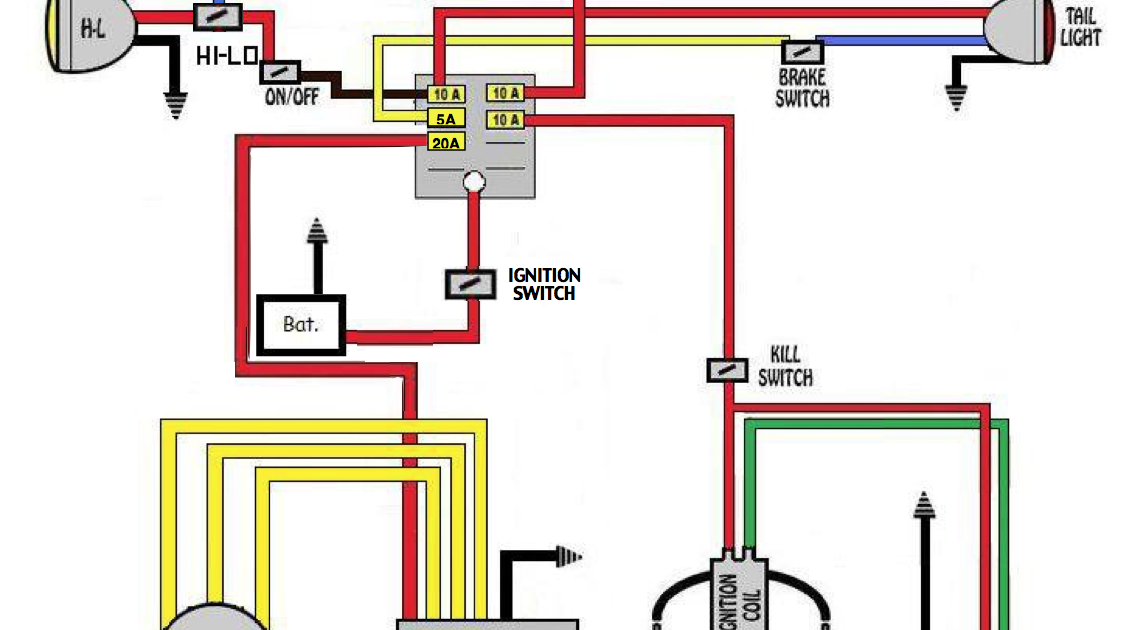
We have a copy of a generic 3-wire voltage regulator wiring diagram available for download. This diagram shows the basic layout and connections. Keep in mind that this is a generic diagram and may not perfectly match your specific motorcycle. Always refer to your service manual for the correct diagram for your bike.
Disclaimer: Electrical repairs should be performed by a qualified technician if you are not comfortable working with electrical systems. Improper repairs can lead to damage to your motorcycle or personal injury.