
Harley Davidson Evolution Engine Diagram
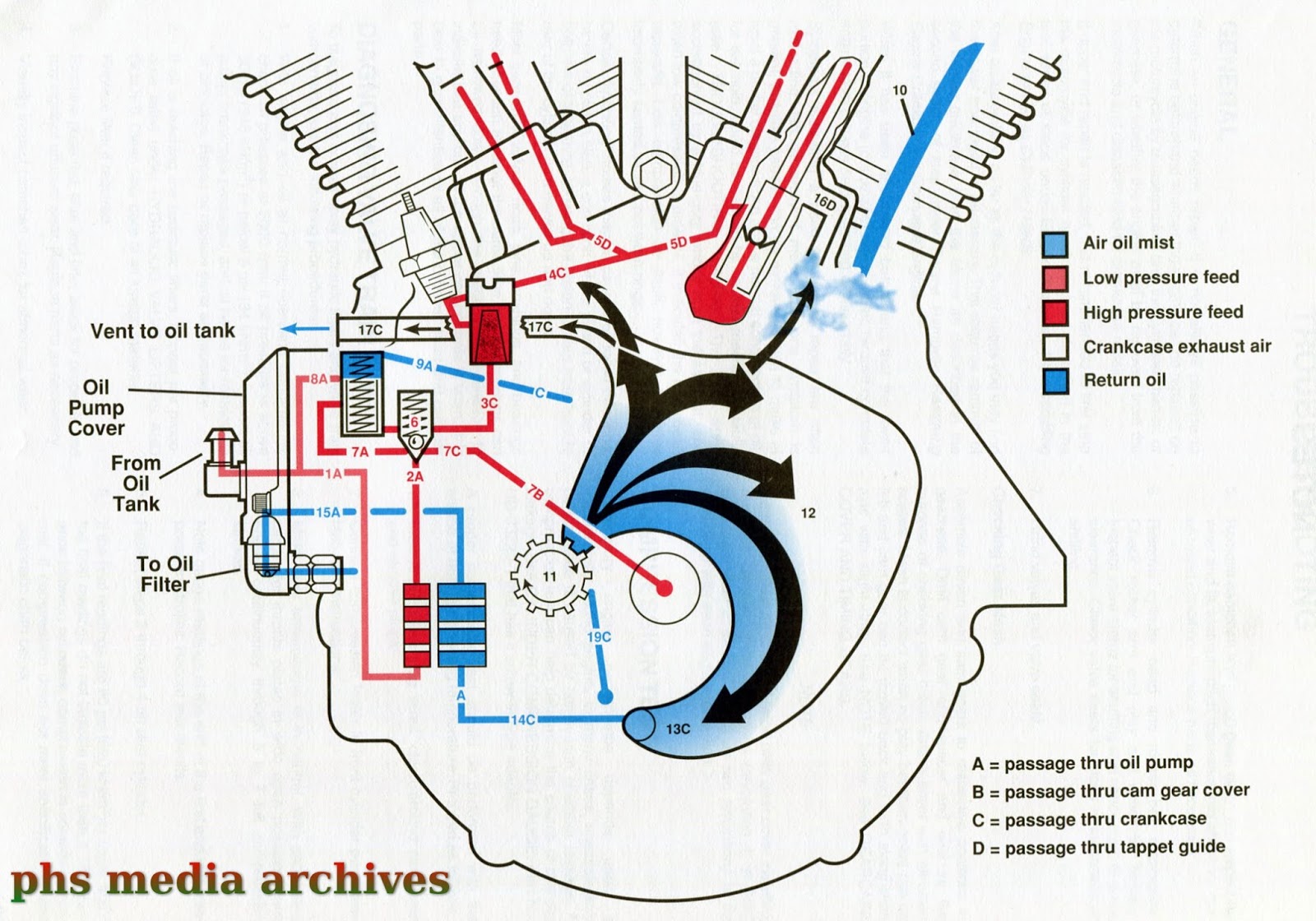
So, you're looking to dive into the guts of a Harley-Davidson Evolution engine, eh? Excellent choice! Whether you're planning a rebuild, troubleshooting a nagging issue, or just plain curious about what makes your Hog tick, understanding the Evolution engine diagram is absolutely crucial. This isn't just some pretty picture; it's your roadmap to navigating the inner workings of a legendary powerplant. We've got a detailed, downloadable diagram ready for you – more on that later – but first, let's break down what you'll be looking at.
Purpose of the Evolution Engine Diagram
Why bother with a diagram? Simple. It provides a visual representation of the engine's components and their relationships. This visual clarity is invaluable for:
- Troubleshooting: Pinpointing the source of a problem quickly and accurately.
- Repairs and Maintenance: Guiding you through disassembly, inspection, and reassembly.
- Modifications: Understanding how modifications will affect the engine's performance.
- Learning: Gaining a deeper understanding of engine operation and design principles.
Think of it as the engine's blueprint. Without it, you're essentially groping in the dark.
Key Specs and Main Parts of the Evolution Engine
The Harley-Davidson Evolution engine, often affectionately called the "Evo," was introduced in 1984 and ran until the introduction of the Twin Cam in 1999 (some models ran longer). Here are some key specs and main components to familiarize yourself with:
Key Specs:
- Displacement: Typically 80 cubic inches (1340cc), although other sizes exist (like the Sportster Evo engines).
- Configuration: 45-degree V-twin, air-cooled.
- Valve Train: Overhead valve (OHV) with hydraulic lifters.
- Fuel Delivery: Initially carburetor, later fuel injection on some models.
Main Parts:
- Crankcase: The foundation of the engine, housing the crankshaft and connecting rods. Typically split into two halves.
- Cylinders: Where the pistons reciprocate, and combustion occurs.
- Pistons: Move up and down within the cylinders, driven by combustion.
- Connecting Rods: Connect the pistons to the crankshaft.
- Crankshaft: Converts the reciprocating motion of the pistons into rotational motion.
- Cylinder Heads: Located atop the cylinders, housing the valves, spark plugs, and combustion chambers.
- Valves (Intake and Exhaust): Control the flow of air/fuel mixture into and exhaust gases out of the cylinders.
- Camshaft: Controls the timing and lift of the valves. Located inside the cam chest.
- Lifters (Hydraulic): Transmit the motion of the camshaft to the pushrods.
- Pushrods: Transfer the motion of the lifters to the rocker arms.
- Rocker Arms: Actuate the valves based on the pushrod movement.
- Carburetor/Fuel Injectors: Mix air and fuel for combustion (carbureted models use a carburetor; later models use fuel injection).
- Ignition System: Provides the spark to ignite the air/fuel mixture (includes coil, distributor or electronic ignition module, and spark plugs).
- Oil Pump: Circulates oil throughout the engine for lubrication and cooling.
Understanding Symbols on the Diagram
The engine diagram uses various lines, colors, and icons to represent different components and their relationships. Here's a breakdown of common symbols:
- Solid Lines: Typically represent physical connections between components (e.g., oil lines, fuel lines).
- Dashed Lines: Often indicate control linkages, vacuum lines, or other non-physical connections.
- Arrows: Show the direction of flow (e.g., oil flow, air flow).
- Colors: May be used to differentiate between different systems (e.g., oil system, fuel system, ignition system). The diagram we're offering you uses standard coloring.
- Icons: Standard engineering symbols represent components like resistors (zigzag line), capacitors (parallel lines), and inductors (coiled wire) within the ignition system if the diagram is detailed enough to show the entire electronic ignition system.
- Numbers/Labels: Correspond to parts lists or exploded views, making identification easier.
Pay close attention to the legend accompanying the diagram; it will explain the specific symbols used.
How the Evolution Engine Works (Simplified)
The Evolution engine operates on the four-stroke principle:
- Intake: The intake valve opens, and the piston moves down, drawing a mixture of air and fuel into the cylinder.
- Compression: Both valves close, and the piston moves up, compressing the air/fuel mixture.
- Combustion (Power): The spark plug ignites the compressed mixture, creating an explosion that forces the piston down.
- Exhaust: The exhaust valve opens, and the piston moves up, pushing the burnt gases out of the cylinder.
This cycle repeats continuously, driving the crankshaft and ultimately the rear wheel. The camshaft controls the timing of the valve opening and closing, while the ignition system provides the spark at the precise moment for optimal combustion. The oil pump ensures that all moving parts are adequately lubricated, preventing wear and overheating.
Real-World Use: Basic Troubleshooting Tips
The Evolution engine is known for its reliability, but problems can still arise. Here are some common issues and how the diagram can help:
- Oil Leaks: Use the diagram to trace oil lines and identify potential leak points (e.g., gaskets, seals, fittings).
- Starting Problems: Check the ignition system components (coil, spark plugs, wiring) using the diagram to ensure proper connections and functionality.
- Poor Performance: Investigate the fuel system (carburetor/fuel injectors, fuel lines) for blockages or malfunctions. Also, check valve timing using the diagram and related service manuals to ensure correct valve operation.
- Excessive Engine Noise: Can be valve train related (lifters, pushrods, rocker arms). Use the diagram to locate these components and inspect them for wear or damage.
Remember to always consult your service manual for detailed troubleshooting procedures and torque specifications. The diagram is a guide, not a replacement for proper service documentation.
Safety Considerations
Working on any engine involves inherent risks. Here are some specific safety concerns related to the Evolution engine:
- High Voltage: The ignition system generates high voltage that can be lethal. Always disconnect the battery before working on the ignition system.
- Hot Surfaces: The engine gets extremely hot during operation. Allow the engine to cool completely before touching any components.
- Flammable Fluids: Gasoline and oil are flammable. Work in a well-ventilated area and keep open flames away.
- Springs and Pressurized Systems: Some components, like valve springs and the oil pump, contain pressurized systems or springs that can cause injury if disassembled improperly. Use caution and follow the service manual instructions carefully.
- Fuel Injection systems: if your Harley-Davidson is fuel injected, always take extreme caution when disconnecting fuel lines. The system is pressurized and fuel will spray if you are not careful.
Safety glasses and gloves are essential when working on any engine. Take your time, be methodical, and always prioritize safety.
Ready to get your hands on that detailed Evolution engine diagram? Just download the file by clicking [link to download]. It will be an invaluable resource for your Harley-Davidson adventures!