Harley Davidson Throttle Body Diagram
Okay, let's dive into the fascinating world of Harley-Davidson throttle bodies. Whether you're diagnosing a rough idle, planning a performance upgrade, or just plain curious about how your hog breathes, understanding the throttle body is crucial. This article will break down a typical Harley throttle body diagram, explain its components, and offer some troubleshooting tips to keep you rolling. And don't worry, we've got a downloadable diagram available for you at the end of this article to use as a reference!
Purpose of the Throttle Body Diagram
Why bother with a throttle body diagram? Several reasons. Firstly, for repairs. When things go wrong – a vacuum leak, a faulty sensor, or a gummed-up butterfly valve – the diagram helps you pinpoint the problem areas. Secondly, for performance modifications. Knowing the components and their functions is essential for selecting the right aftermarket parts and tuning your engine. Finally, for education. Even if you're not planning on tearing into your engine, understanding how the throttle body works provides a fundamental knowledge of internal combustion engines, and a deeper appreciation of your motorcycle.
Key Specs and Main Parts
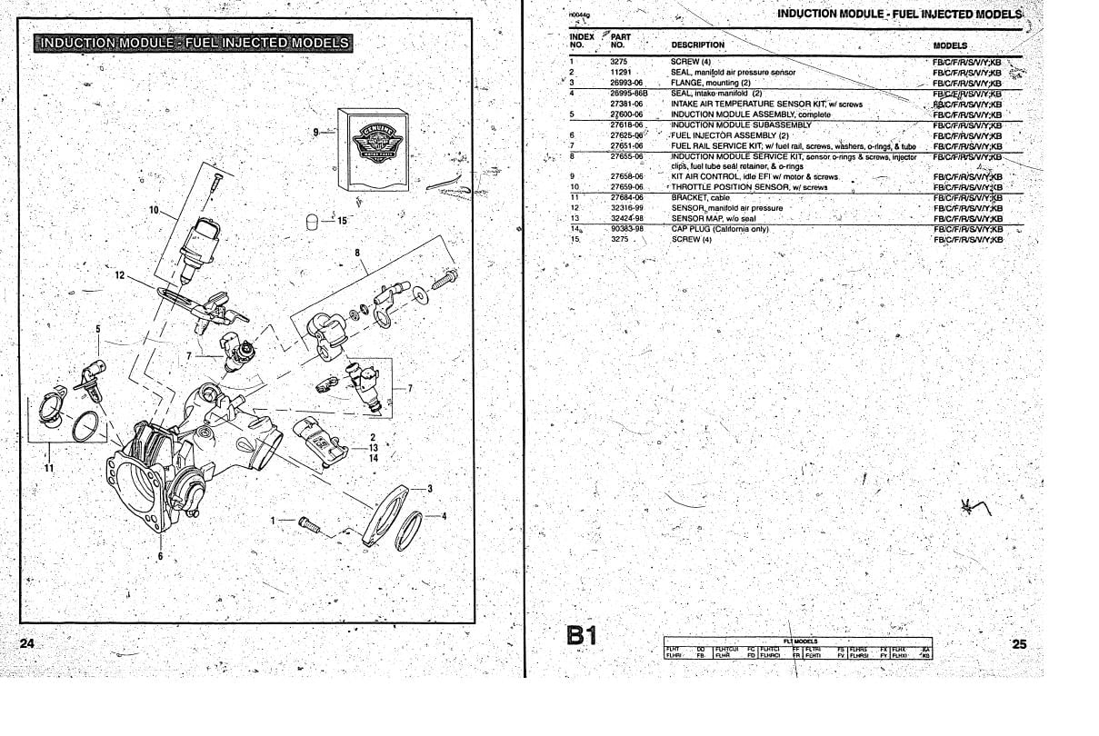
While specific throttle body designs vary between Harley models (CV carburetors on older models, electronic throttle control on newer ones), the basic principles remain the same. Here’s a rundown of the key components often shown on a diagram:
Throttle Body Housing
This is the main body – usually cast aluminum – that houses all the other components. It includes the intake opening where air enters and the mounting flange where the throttle body attaches to the intake manifold.
Throttle Plate (Butterfly Valve)
The throttle plate, or butterfly valve, is a circular plate inside the throttle bore that rotates to control airflow into the engine. It's connected to the throttle cable (or electric motor in Electronic Throttle Control (ETC) systems).
Throttle Position Sensor (TPS)
The TPS is a potentiometer that measures the throttle plate's angle. This signal is sent to the Engine Control Module (ECM) so the ECM knows how much power is being requested and can adjust fuel injection and timing accordingly. This is a critical component for proper engine operation.
Idle Air Control (IAC) Valve
The IAC valve regulates the amount of air that bypasses the throttle plate when it's closed, maintaining a stable idle speed. It's usually controlled by the ECM.
Fuel Injectors
In fuel-injected Harleys, fuel injectors spray fuel into the intake stream. The ECM controls the injector pulse width (the amount of time the injector is open) to regulate the air-fuel ratio. Older carbureted models of course will not have this and instead rely on the carburetor’s circuits for fuel delivery.
Manifold Absolute Pressure (MAP) Sensor
The MAP sensor measures the pressure inside the intake manifold. This provides the ECM with information about engine load and is used to calculate the required amount of fuel.
Vacuum Ports
These ports provide vacuum for various systems, such as the fuel pressure regulator, or in older models, the vacuum advance for the ignition timing.
Coolant Passages (If Applicable)
Some throttle bodies have coolant passages to warm the throttle body and prevent icing in cold weather.
Symbols – Understanding the Diagram
Throttle body diagrams are technical drawings and use specific symbols to represent different components and connections. Here's a breakdown of common symbols:
- Solid Lines: Typically represent physical connections, such as hoses, wires, or mechanical linkages.
- Dashed Lines: Often indicate vacuum lines or reference signals.
- Arrows: Show the direction of flow, such as air, fuel, or coolant.
- Circles/Squares: Represent sensors, valves, or other electrical components. These components often have accompanying labels identifying their function, like TPS, IAC, or MAP.
- Colors: Different colors may be used to differentiate between different types of fluids or signals. For example, blue might represent coolant, while red represents fuel. The specific color coding varies by manufacturer and diagram, so always check the legend.
Pay close attention to the legend or key on the diagram. This will explain any unique symbols or color codes used in that particular drawing.
How It Works
The throttle body's primary function is to control the amount of air entering the engine. When you twist the throttle, the throttle plate opens, allowing more air to flow into the intake manifold. The ECM reads the TPS signal and uses this information, along with data from the MAP sensor and other sensors, to determine the correct amount of fuel to inject. The IAC valve regulates airflow during idle to maintain a steady engine speed. The synchronized dance between air and fuel ensures optimal combustion and performance.
In systems with Electronic Throttle Control (ETC), there isn't a direct mechanical linkage between the throttle grip and the throttle plate. Instead, the throttle grip position is read by a sensor, and the ECM controls a servo motor that opens and closes the throttle plate. This allows for more sophisticated engine management strategies, such as traction control and cruise control.
Real-World Use – Basic Troubleshooting Tips
Here are a few basic troubleshooting tips that you can use with the diagram:
- Rough Idle: Check the IAC valve and its connections. A dirty or faulty IAC valve can cause an unstable idle. Look for vacuum leaks around the throttle body and intake manifold.
- Poor Performance: Check the TPS. A faulty TPS can send incorrect information to the ECM, leading to poor acceleration and fuel economy. Use a multimeter to verify the TPS output voltage changes smoothly as the throttle is opened. Also check for clogged fuel injectors.
- Check Engine Light (CEL): Use a diagnostic scan tool to read the trouble codes. The codes will often point to a specific sensor or component in the throttle body system. The diagram can then help you locate and test that component.
- Vacuum Leaks: Use a spray bottle filled with soapy water to check for vacuum leaks around the throttle body and intake manifold. Spray the soapy water around the gaskets and connections. If you see bubbles forming, that indicates a vacuum leak.
Safety – Handle with Care
Working on the throttle body involves dealing with several potentially risky components. Fuel injectors are under high pressure, so always relieve fuel pressure before disconnecting any fuel lines. Electrical components can be damaged by static electricity, so use proper grounding techniques. Be extremely careful when working around moving parts, such as the throttle plate, and never start the engine with the throttle body disassembled.
Important: Disconnecting the battery before working on electrical components is always a good practice. Remember to consult your Harley-Davidson service manual for specific instructions and safety precautions for your model. Also, be aware of the potential for flammable materials (fuel) when working on or around the fuel injection system. Have a fire extinguisher nearby.
Always double-check your work before starting the engine. A loose connection or a misplaced hose can lead to serious engine damage. When in doubt, consult a qualified mechanic.
Now that you have a solid understanding of throttle body diagrams and their components, you're well-equipped to diagnose problems, plan modifications, and gain a deeper appreciation for the inner workings of your Harley-Davidson. So, are you ready to get that diagram we mentioned at the start?
As promised, we have a general Harley-Davidson throttle body diagram available for you to download. Please contact us to get access to this file.