Harley Voltage Regulator Wiring Diagram
So, you're looking to understand the Harley Davidson voltage regulator wiring diagram, huh? Good choice. This diagram is your secret weapon when it comes to diagnosing charging system issues, performing upgrades, or even just gaining a deeper understanding of how your bike ticks. Think of it as the roadmap to keeping your battery happy and your ride smooth. We're going to break it down in a way that's clear, concise, and helpful, even if you're not an electrical engineer.
Purpose of Understanding the Wiring Diagram
Let's be clear: having a solid understanding of the voltage regulator wiring diagram isn't just about impressing your buddies at the bike night. It's about practical problem-solving. You'll use it for:
- Troubleshooting Charging Issues: Is your battery constantly dying? Diagram to the rescue.
- Performing Upgrades: Swapping out components? The diagram will guide you through the wiring changes.
- Preventive Maintenance: Understanding the system helps you identify potential problems before they leave you stranded.
- Custom Builds: Modifying your Harley? The diagram is essential for integrating the charging system with your custom wiring.
Key Specs and Main Parts
Before diving into the specifics, let's identify the key players and their roles. While diagrams may vary slightly based on the Harley model and year, the fundamental components remain largely the same. Keep in mind that newer bikes may use more complex systems, including CAN-bus communication, which complicates things but doesn't change the core functionality of the voltage regulator itself.
- Stator: The heart of your charging system. It's essentially a miniature generator, producing AC (Alternating Current) electricity as the engine spins.
- Voltage Regulator: The brain. This device converts the AC current from the stator to DC (Direct Current) and, more importantly, regulates the voltage to a safe level for charging the battery (typically around 13.8-14.5 volts). Overcharging can kill your battery!
- Rectifier: Often integrated into the voltage regulator, the rectifier converts the AC current from the stator to DC current. Think of it as a one-way street for electrons.
- Battery: The energy storage device that powers your bike's electrical system.
- Fuses/Circuit Breakers: Safety devices that protect the system from overloads.
- Wiring Harness: The network of wires that connects all the components.
Key Specs: Understanding voltage and current ratings is crucial. The stator's output voltage and current capacity determine the charging system's overall capability. The voltage regulator must be rated to handle the stator's output and provide the correct charging voltage for the battery.
Symbols, Lines, Colors, and Icons
Deciphering the symbols on a wiring diagram is like learning a new language. Here's a breakdown:
- Lines: Represent wires. Different line thicknesses might indicate different wire gauges (thicker lines generally indicate wires that carry more current).
- Colors: Wires are color-coded for easy identification. Common colors include red (positive), black (ground), and various other colors for specific circuits (e.g., blue for lighting). A legend on the diagram will always clarify color codes.
- Symbols:
- Battery: Usually represented by a series of short and long parallel lines.
- Voltage Regulator: A rectangular box with input and output terminals.
- Stator: A circle with a wavy line inside, representing the AC output.
- Ground: A series of downward-pointing lines, often resembling an inverted Christmas tree.
- Fuse: A line with a loop or a "Z" shape in the middle.
- Circuit Breaker: Similar to a fuse, but often with a small box alongside the symbol indicating its reset capability.
- Connectors: Represented by circles or squares where wires connect to components or other wires.
The diagram will also indicate the polarity of the wires (+ for positive, - for negative/ground). Pay close attention to this! Reversing polarity can cause serious damage.
How It Works: The Charging Cycle
Here's the simplified version of how the Harley charging system operates:
- The engine spins the rotor, which in turn rotates magnets within the stator. This generates AC electricity.
- The AC electricity from the stator flows to the voltage regulator.
- The rectifier, integrated within the voltage regulator, converts the AC current to DC current.
- The voltage regulator monitors the battery voltage. If the voltage is below the setpoint (e.g., 13.8V), the regulator allows current to flow to the battery, charging it. If the battery is fully charged (e.g., 14.5V), the regulator reduces or stops the current flow to prevent overcharging.
- The battery then powers the bike's electrical system.
The regulator uses various techniques to control the charging current, such as shunt regulation (where excess current is diverted to ground as heat) or series regulation (where the current flow is actively controlled). The specific method depends on the regulator design.
Real-World Use: Basic Troubleshooting Tips
Armed with the wiring diagram, you can tackle common charging system problems:
- No Charging: Check the stator output voltage with a multimeter. If there's no output, the stator might be faulty. Also, check the voltage regulator input. If voltage is present at the input but not the output, the regulator is likely the culprit.
- Overcharging: Use a multimeter to check the battery voltage while the engine is running. If the voltage exceeds 14.5V, the voltage regulator is likely malfunctioning.
- Battery Draining: A parasitic draw can drain your battery even when the bike is off. Use a multimeter to measure the current draw with the ignition off. The wiring diagram can help you isolate the circuit causing the draw.
- Blown Fuses: Repeatedly blown fuses indicate a short circuit. The wiring diagram will help you trace the circuit and identify the location of the short.
Remember to always consult your bike's specific service manual for detailed troubleshooting procedures.
Safety: Risky Components
Working with electrical systems can be dangerous. Here are some key safety precautions:
- Disconnect the Battery: Always disconnect the negative (-) battery terminal before working on any electrical components. This prevents accidental short circuits.
- High Voltage: The stator can produce high voltages, especially at higher engine speeds. Be careful when testing stator output.
- Heat: Voltage regulators can get hot, especially shunt-type regulators. Avoid touching them immediately after the engine has been running.
- Proper Grounding: Ensure all ground connections are clean and secure. Poor grounding can cause voltage drops and electrical problems.
- Use the Right Tools: Use insulated tools designed for electrical work.
Always double-check your wiring before reconnecting the battery. Incorrect wiring can cause serious damage to your bike's electrical system.
Important: Electricity doesn't forgive mistakes. If you are uncomfortable working with electrical systems, seek the assistance of a qualified mechanic.
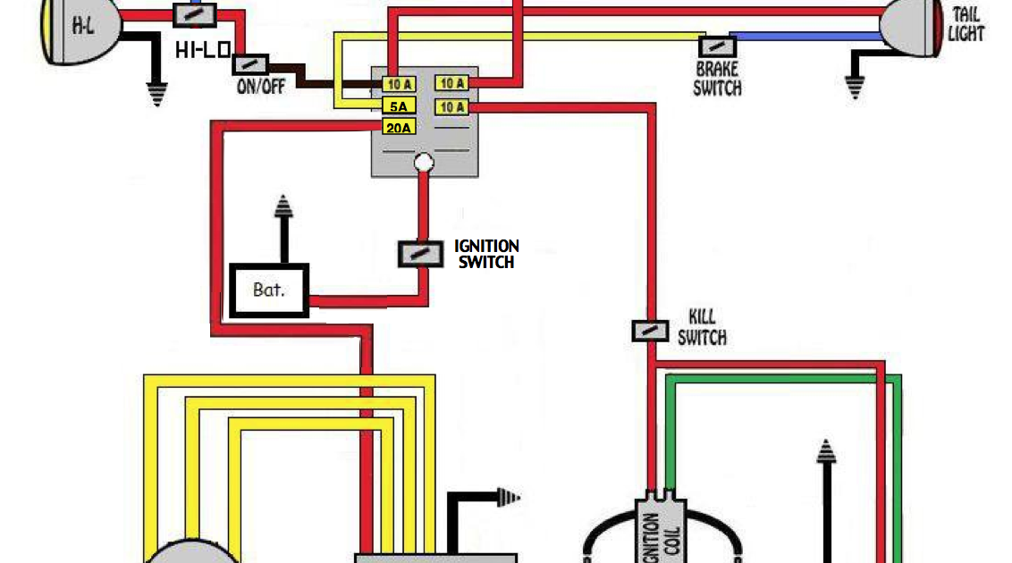
We have a high-resolution, printable version of the voltage regulator wiring diagram available for download. This diagram is a generic example, and the specific diagram for your Harley may differ. Be sure to consult your service manual for the correct diagram for your bike's year and model.