Harness 1994 Chevy Truck Wiring Diagram Free
Let's talk about the wiring diagram for a 1994 Chevy Truck. Whether you're diving into a repair, performing modifications, or just expanding your automotive knowledge, understanding the wiring harness is crucial. This document is your roadmap through the electrical system, guiding you past potential pitfalls and empowering you to tackle electrical issues with confidence. And yes, we have a free, downloadable diagram ready for you at the end of this article!
Purpose: Your Electrical Roadmap
The wiring diagram for your 1994 Chevy Truck is more than just a collection of lines and symbols; it's a comprehensive visual representation of the entire electrical system. Its primary purposes include:
- Troubleshooting: Identifying the source of electrical problems, such as shorts, open circuits, or faulty components.
- Repair: Accurately repairing damaged wiring or replacing defective parts.
- Modification: Safely adding aftermarket accessories, like stereos, lights, or alarm systems.
- Understanding: Gaining a deeper understanding of how the truck's electrical system operates.
- Restoration: Assisting in the restoration of classic trucks to their original specifications.
Without a proper wiring diagram, you're essentially working blind, increasing the risk of misdiagnosis, further damage, and even personal injury.
Key Specs and Main Parts
The 1994 Chevy Truck wiring harness is a complex network of wires, connectors, and components that power various systems throughout the vehicle. Key specifications to consider when working with it include:
- Voltage: Primarily a 12-volt DC system.
- Wire Gauge: Varying gauges (e.g., 10 AWG, 12 AWG, 16 AWG) depending on the current requirements of the circuit. Larger gauge wires handle more current.
- Fuses and Relays: Protection and switching mechanisms strategically placed throughout the system.
- Grounding Points: Critical for completing circuits and preventing electrical noise.
- Connectors: A wide variety of connectors used to join wiring harnesses and components.
The main parts of the wiring harness can be broadly categorized into sections such as:
- Engine Wiring: Covers sensors, actuators, and ignition components.
- Body Wiring: Interior lights, power windows, door locks, etc.
- Lighting Wiring: Headlights, taillights, turn signals, and marker lights.
- Instrument Panel Wiring: Gauges, indicators, and warning lights.
Decoding the Symbols: Your Visual Language
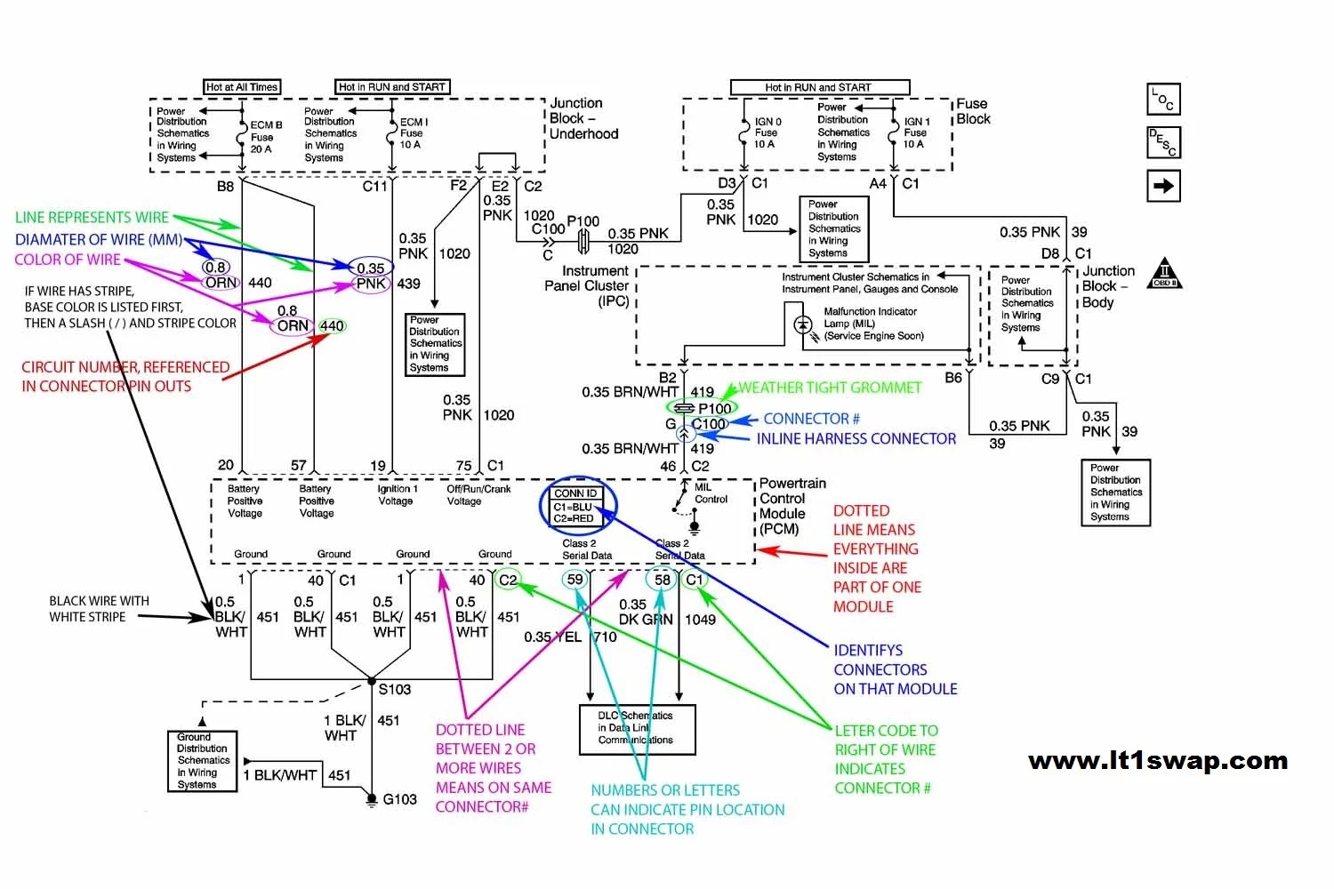
Wiring diagrams use a standardized set of symbols to represent electrical components and connections. Understanding these symbols is key to interpreting the diagram correctly.
- Lines: Represent wires, with different thicknesses indicating wire gauge. Solid lines typically indicate positive or powered circuits, while dashed lines might represent ground or control circuits.
- Colors: Each wire is identified by a specific color code (e.g., RED, BLK, WHT, GRN). Color codes are essential for identifying and tracing wires in the actual harness.
- Ground Symbol: Usually depicted as a series of horizontal lines descending to ground.
- Fuse Symbol: A wavy line enclosed in a rectangle, indicating an overcurrent protection device.
- Relay Symbol: A coil symbol (representing the electromagnet) and a switch symbol (representing the contacts).
- Resistor Symbol: A zigzag line, representing an electrical resistance.
- Diode Symbol: A triangle pointing to a vertical line, indicating a one-way flow of current.
- Switch Symbol: Shows the open or closed state of a switch.
- Connector Symbol: A circle or square with a number indicating the number of pins.
Pay close attention to the legend or key on the wiring diagram, as it will provide a comprehensive explanation of all the symbols used. Some symbols can vary slightly depending on the manufacturer and the specific diagram.
How It Works: Following the Electrical Flow
The wiring diagram illustrates the flow of electricity through the various circuits in your truck. Understanding this flow is essential for troubleshooting. Electricity flows from the battery (positive terminal), through the circuit components (e.g., switches, relays, loads), and back to the battery (negative terminal or ground). When a circuit is complete, current can flow and the connected component will function.
Each circuit on the diagram is usually drawn in a simplified form, showing only the essential components and connections. By tracing the path of a specific circuit, you can identify all the components that are involved in its operation. This allows you to pinpoint potential points of failure. For example, if your headlights are not working, you can trace the headlight circuit on the diagram to identify the fuse, switch, relay, and wiring that are involved. By testing each of these components, you can isolate the cause of the problem.
Remember to always disconnect the negative battery terminal before working on any electrical components.
Real-World Use: Basic Troubleshooting Tips
Here are some basic troubleshooting tips using the wiring diagram:
- No Power: Use a multimeter to check for voltage at different points in the circuit. Start at the fuse and work your way through the circuit. If you find a point where voltage is missing, the problem is likely between that point and the last point where you had voltage.
- Short Circuit: A short circuit occurs when current flows through an unintended path, usually directly to ground. This can cause a fuse to blow or damage components. Use the wiring diagram to identify potential short circuit locations and inspect the wiring for damage.
- Open Circuit: An open circuit occurs when the circuit is broken, preventing current from flowing. This can be caused by a broken wire, a loose connection, or a faulty component. Use a multimeter to check for continuity (a complete path) between different points in the circuit.
- Component Failure: If a component is not functioning correctly, use the wiring diagram to identify the circuit it is part of and test the component according to the manufacturer's specifications.
Example Scenario: Your turn signals aren't working. Consult the wiring diagram, locate the turn signal circuit, identify the fuse, flasher relay, switch, and bulbs. Check the fuse first. If it's good, test the flasher relay. If the relay is good, check the switch. Finally, inspect the bulbs and wiring for any damage. Using the diagram ensures you test components in the correct order and efficiently.
Safety First: Highlighting Risky Components
Working with automotive electrical systems can be dangerous. Always disconnect the negative battery terminal before working on any electrical components. Pay special attention to the following components:
- Battery: The battery stores a significant amount of energy and can cause burns or explosions if mishandled.
- High-Voltage Circuits: Some circuits, such as those related to the ignition system, can carry high voltage even with the battery disconnected. Exercise extreme caution when working on these circuits.
- Airbag System: The airbag system is a highly sensitive system and can deploy unexpectedly if mishandled. Refer to the service manual for specific safety precautions before working on this system.
Warning: Always use appropriate safety equipment, such as safety glasses and insulated gloves, when working on electrical systems. If you are not comfortable working on electrical systems, consult a qualified technician.
By understanding the purpose, components, symbols, and flow of electricity within the 1994 Chevy Truck wiring harness, you'll be well-equipped to tackle a variety of electrical tasks. You will be empowered to troubleshoot, repair, and modify your truck's electrical system with confidence and precision.
Download Your Free 1994 Chevy Truck Wiring Diagram
Ready to get started? You can download the wiring diagram we've been discussing right here: [LINK TO DOWNLOAD - REPLACE THIS WITH ACTUAL LINK]. Good luck, and remember to prioritize safety!