High Flo Gold Series Pump Parts Diagram
Alright, let's dive into the High Flo Gold Series pump parts diagram. This isn't just a pretty picture; it's your roadmap for understanding, maintaining, and potentially repairing your high-performance fuel pump. Whether you're chasing that extra horsepower, troubleshooting a fuel delivery issue, or simply want to know what's ticking under the hood, this diagram is essential. Think of it as the pump's DNA sequence – it reveals everything.
Why This Diagram Matters
Forget guesswork. This detailed parts diagram allows you to:
- Accurately identify components within the pump. No more generic terms – you'll know the exact name and function of each part.
- Diagnose problems effectively. By referencing the diagram, you can pinpoint the source of a problem, whether it's a worn-out check valve or a damaged rotor.
- Perform repairs and maintenance with confidence. Knowing the correct part number and its location ensures you order the right replacement and install it properly.
- Deepen your understanding of fuel pump operation. This helps in troubleshooting more complex fuel system issues and makes you a more capable DIY mechanic.
- Verify compatibility. If you're modifying your fuel system, the diagram helps ensure the pump is compatible with your specific application.
Key Specs and Main Parts
The High Flo Gold Series pump is typically a roller-vane or gerotor-type pump, known for its high flow rate and reliability. Let's break down the key components:
- Pump Housing: The robust outer shell that protects all internal components. Material usually consists of anodized aluminum for durability and corrosion resistance.
- Electric Motor: A DC motor that drives the pumping mechanism. Specs to look for include voltage (usually 12V or 16V), current draw (amps), and rated RPM. High Flo pumps usually have upgraded motors capable of higher duty cycles.
- Rotor/Vane Assembly (or Gerotor): This is the heart of the pump. In a roller-vane pump, a rotor with spring-loaded vanes rotates within a chamber, creating suction and pressure. A gerotor uses two interlocking gears to achieve the same effect. Check the diagram for the specific type.
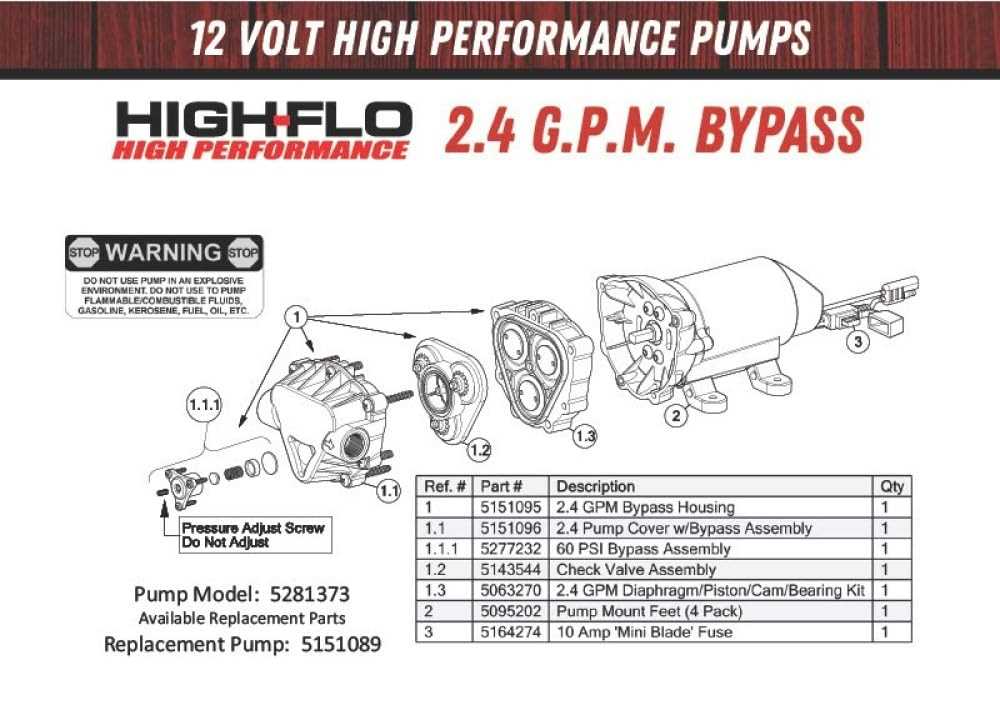
- Check Valve: Prevents fuel from flowing back into the tank when the pump is off, maintaining fuel pressure in the lines. A faulty check valve can lead to hard starting issues. Look for the part number and the opening pressure if specified.
- Pressure Relief Valve (PRV): Protects the fuel system from over-pressurization. If the fuel pressure exceeds the set limit, the PRV opens, bypassing fuel back to the inlet side of the pump. Crucial for preventing damage to fuel lines and injectors.
- Fuel Inlet and Outlet Fittings: These are the connections for the fuel lines. Common sizes are AN (Army-Navy) fittings, which offer a secure and leak-free connection. Note the thread size and type (e.g., -6AN, -8AN).
- Electrical Connector: Provides power to the pump motor. Check for polarity and pin configuration. Many High Flo pumps come with a weather-resistant connector.
- Filters/Strainers: Located at the inlet to prevent debris from entering and damaging the pump. Essential for pump longevity. The micron rating indicates the size of particles it filters.
Decoding the Diagram: Symbols and Conventions
The diagram uses standard engineering conventions to represent different components and connections. Here's what you need to know:
- Solid Lines: Represent physical connections between parts. A thicker line might indicate a primary fuel flow path.
- Dashed Lines: Often indicate secondary or auxiliary connections, such as electrical wiring or venting lines.
- Arrows: Indicate the direction of fuel flow. Pay close attention to these arrows when troubleshooting.
- Circles and Squares: Often represent fittings, seals, or other connection points.
- Part Numbers: Each part should have a unique identifier. Use these numbers when ordering replacements. They're usually listed next to each component on the diagram.
- Cross-sections: Some diagrams might include cutaway views to show the internal workings of a component.
- Abbreviations: Common abbreviations include "IN" (inlet), "OUT" (outlet), "PRV" (pressure relief valve), and "PSI" (pounds per square inch).
How It Works: A Simplified Explanation
In a nutshell, the High Flo Gold Series pump works like this:
- The electric motor receives power and begins to rotate.
- The rotating motor drives the rotor/vane (or gerotor) assembly.
- The rotating assembly creates a vacuum on the inlet side of the pump, drawing fuel from the fuel tank through the inlet filter/strainer.
- The rotating assembly then forces the fuel through the outlet, increasing its pressure.
- The check valve prevents fuel from flowing back to the tank when the pump is off.
- The pressure relief valve protects the system from over-pressurization.
Real-World Use: Basic Troubleshooting
Here are some common problems and how the diagram can help:
- Pump Not Working: Check the electrical connector for proper connection and voltage. Use the diagram to trace the wiring and identify potential shorts or open circuits.
- Low Fuel Pressure: Could be a clogged filter/strainer (check the inlet side), a worn rotor/vane assembly (inspect for damage), or a faulty check valve (test for backflow).
- Excessive Noise: Could indicate a worn bearing in the motor (replace the motor) or cavitation due to a restricted inlet (check for clogged filters or kinked fuel lines).
- Fuel Leak: Identify the source of the leak using the diagram. Common leak points are around fittings, seals, and the pump housing.
Safety First! Risky Components
Working with fuel systems requires caution. Here's what to watch out for:
- Fuel: Highly flammable and potentially explosive. Disconnect the battery before working on the fuel system to prevent sparks. Work in a well-ventilated area and have a fire extinguisher nearby.
- Electrical Components: Disconnect the battery to avoid electrical shock.
- High Pressure: Fuel lines can be under significant pressure, even when the engine is off. Relieve pressure before disconnecting any lines.
- Used Fuel Filters: Handle with care. They can contain contaminants. Dispose of properly.
Always prioritize safety when working on any fuel system component. If you are unsure about any procedure, consult a qualified mechanic.
Consult the pump's datasheet for all performance specs and flow rate. Also, ensure the new pump flow rate is compatible with the engine's performance target after the mod.
With the High Flo Gold Series pump parts diagram, you're well-equipped to understand and maintain your high-performance fuel pump. Good luck!
We have the file, and the diagram can be downloaded here.