
Holley Terminator X Ls Wiring Harness
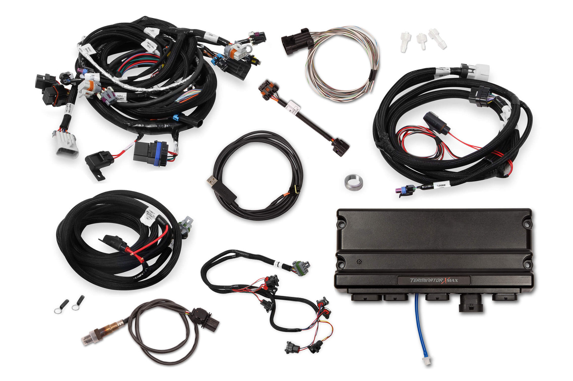
So, you're tackling a Holley Terminator X LS swap? Excellent choice! These systems offer incredible control and tunability. But let's be honest, wiring can be intimidating. This article breaks down the Holley Terminator X LS wiring harness, explaining its purpose, key components, how it works, and even some troubleshooting tips to get you started. Think of this as your detailed roadmap to a successful install.
Why This Wiring Harness Matters
Understanding the Terminator X LS wiring harness is absolutely crucial for a few key reasons:
- Installation: Obviously, knowing where each wire goes is paramount to getting your system up and running. A missed connection or incorrect splice can lead to serious issues.
- Troubleshooting: When (not if, when) problems arise, a solid grasp of the wiring will significantly speed up the diagnostic process. No more blindly poking around with a multimeter!
- Modification: Maybe you want to add sensors, auxiliary outputs, or integrate other systems. Knowing the harness inside and out will allow you to do so safely and effectively.
- Learning: Even if you're not planning a swap yourself, understanding the principles behind this harness can greatly improve your overall automotive knowledge.
With this article, you will be able to approach repairs, modifications, and new learning experiences with confidence and safety. And remember, we have the full wiring diagram available for download!
Key Specs and Main Parts
The Holley Terminator X LS harness is designed to be a standalone system, controlling the engine's vital functions. Here's a breakdown of the key components and specifications you should be aware of:
- ECU Connector: This is the brain of the operation – the main connection point for all the sensor inputs and output controls.
- Power and Ground Wires: These are your essential connections to the vehicle's electrical system. Important: Always ensure proper gauge wiring and secure connections!
- Sensor Connectors: These connect to various sensors such as:
- Crankshaft Position (CKP) Sensor: Monitors crankshaft position for timing and RPM.
- Camshaft Position (CMP) Sensor: Monitors camshaft position for sequential fuel injection and ignition.
- Manifold Absolute Pressure (MAP) Sensor: Measures intake manifold pressure for load calculations.
- Throttle Position Sensor (TPS): Measures throttle plate angle for throttle input.
- Coolant Temperature Sensor (CTS): Measures engine coolant temperature.
- Air Temperature Sensor (ATS/IAT): Measures intake air temperature.
- Oxygen (O2) Sensors: Measure exhaust oxygen content for fuel mixture control.
- Injector Connectors: These connect to the fuel injectors, delivering fuel to the cylinders. They are usually grouped into banks.
- Coil Connectors: These connect to the ignition coils, providing the spark for combustion. Again, usually grouped into banks.
- Transmission Connectors: If you're using an electronically controlled transmission, the harness will include connectors for transmission sensors and solenoids.
- Fuel Pump Relay Control Wire: Provides a signal to activate the fuel pump relay.
- Fan Control Relay Wires: Provide signals to activate electric cooling fan relays.
- Diagnostic Connector (OBDII): Allows you to connect a scan tool for diagnostics and data logging.
Symbols: Decoding the Wiring Diagram
Understanding the symbols used in the wiring diagram is crucial. Here's a breakdown of common symbols:
- Solid Lines: Represent wires. The thickness of the line may or may not indicate wire gauge (refer to the legend).
- Dashed Lines: Often represent shielded cables or connections that are not directly wired (e.g., a CAN bus connection).
- Color Codes: Each wire is typically identified by a color code (e.g., RED, BLU, GRN/WHT - Green with White Stripe). Always double-check the color coding with the physical wire.
- Connectors: Represented by various shapes (circles, squares, rectangles) with pins indicated by numbers.
- Ground Symbol: Typically a series of downward pointing triangles, indicating a connection to chassis ground.
- Relay Symbol: A square with a coil and switch contacts, indicating a relay.
- Sensor Symbols: Vary depending on the sensor type. Look for common symbols like resistors, potentiometers, or inductors.
Also, carefully study the diagram legend. It will tell you exactly what each symbol and color represents in your specific harness.
How It Works: The Big Picture
The Terminator X LS harness acts as the communication network between the ECU and all the engine's components. The ECU receives signals from the sensors, processes that data, and then sends commands to the actuators (injectors, coils, relays). Here’s a simplified overview:
- Sensor Inputs: Sensors like the CKP, CMP, MAP, TPS, CTS, and IAT send data to the ECU.
- Data Processing: The ECU uses this data to calculate fuel injection timing, ignition timing, and other parameters based on pre-programmed tables and algorithms.
- Actuator Outputs: The ECU sends signals to the injectors to control fuel delivery, to the coils to control ignition timing, and to relays to control devices like the fuel pump and cooling fans.
- Feedback Loop: The O2 sensors provide feedback on the exhaust gas composition, allowing the ECU to make adjustments to the fuel mixture in real-time.
The beauty of the Terminator X system is its flexibility. You can customize many of these parameters to optimize your engine's performance.
Real-World Use: Basic Troubleshooting
Here are a few basic troubleshooting tips using the wiring harness as a guide:
- No Start:
- Check power and ground connections to the ECU. Use a multimeter to verify voltage.
- Verify the CKP and CMP sensor signals. Use a scan tool or oscilloscope.
- Check the fuel pump relay control wire. Is the relay being activated when you turn the key?
- Rough Idle:
- Check for vacuum leaks.
- Verify the TPS signal is within range.
- Check the O2 sensor readings.
- Engine Misfire:
- Check the coil connectors and wiring.
- Verify the injector connectors and wiring.
Pro Tip: When troubleshooting, always start with the simplest things first. Check fuses, relays, and connections before diving into more complex diagnostics.
Safety First: Highlighting Risky Components
Working with automotive electrical systems can be dangerous. Here are some key safety considerations:
- Battery Disconnect: Always disconnect the negative battery terminal before working on any electrical components. This prevents accidental shorts and potential damage to the ECU.
- Fuel System: Be extremely careful when working around fuel injectors and fuel lines. Fuel is highly flammable.
- High Voltage: Ignition coils generate high voltage. Avoid touching the coil connectors or wires while the engine is running.
- Proper Tools: Use proper crimping tools and connectors to ensure secure and reliable connections.
- Wire Gauge: Always use the correct wire gauge for the application. Undersized wires can overheat and cause fires.
- Shielded Cables: When dealing with shielded cables (e.g., for the CKP sensor), ensure the shield is properly grounded.
Important: Never probe wires that have a risk of carrying high current with bare hands. Always use insulated tools and proper personal protective equipment (PPE). Double check that the ignition is off.
By now, you should have a much better understanding of the Holley Terminator X LS wiring harness. Remember to take your time, double-check your connections, and always prioritize safety. With the right knowledge and a bit of patience, you can confidently tackle your LS swap project. Happy wiring! Oh and one last note: remember we have the complete wiring diagram available for download. Get it now to make life easier!