
Honda 4 Pin Alternator Wiring Diagram
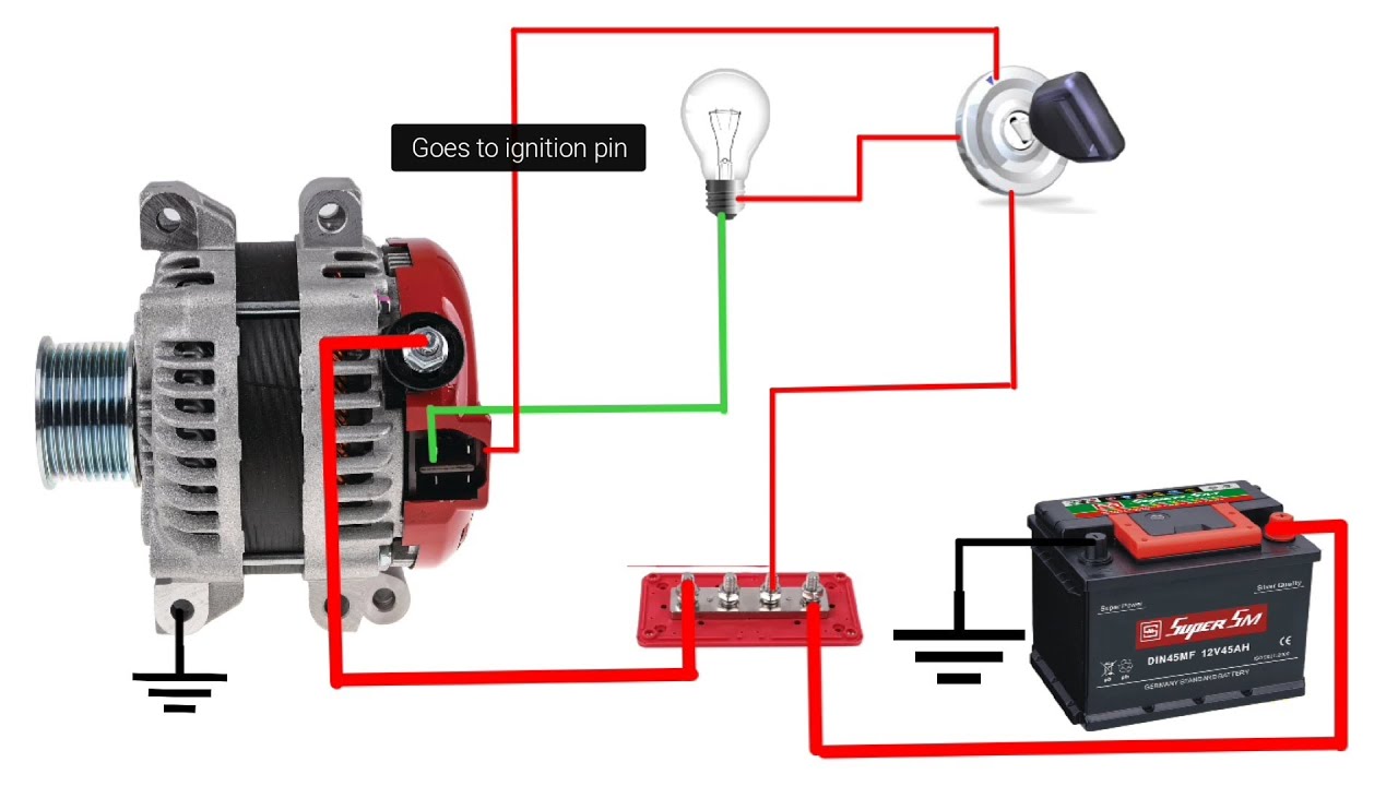
Understanding the Honda 4-pin alternator wiring diagram is crucial for anyone tackling electrical repairs, modifications, or even just wanting a deeper understanding of their vehicle's charging system. This isn't just about swapping out parts; it's about diagnosing issues, ensuring proper connections, and preventing potentially damaging electrical problems. Whether you're upgrading your audio system, troubleshooting a battery drain, or simply performing routine maintenance, knowing how your alternator interacts with the rest of the electrical system is invaluable.
Key Specs and Main Parts
The 4-pin alternator, commonly found in many Honda vehicles, utilizes a specific set of connections to regulate charging voltage and communicate with the vehicle's ECU (Engine Control Unit). Before diving into the wiring diagram, let's identify the key components and their functions:
- Battery Terminal (B+): This is the main output terminal. It's a heavy-gauge wire connected directly to the positive (+) terminal of the battery, supplying charging current to the entire electrical system. Expect to see a thick wire and a high current rating here.
- Ignition Terminal (IG or IGN): This terminal is connected to the ignition switch and receives voltage when the key is in the "ON" position. It energizes the alternator's regulator, essentially telling it to start charging when the engine is running. Without this, the alternator won't "wake up."
- Lamp Terminal (L): Also known as the charge indicator terminal. This connection goes to the charging system warning light (battery light) on your dashboard. The ECU monitors the voltage at this terminal. When the voltage is low (alternator not charging properly), the light illuminates.
- Field Control Terminal (FR or C): This terminal is the *field control* connection. It allows the ECU to control the alternator's output based on various factors, such as engine load, battery voltage, and other system demands. This ECU control optimizes fuel efficiency and reduces strain on the alternator. This is a more modern feature than older 3-wire alternators.
Symbols, Lines, and Colors
A wiring diagram is a visual language. Understanding the symbols is key to interpretation. Expect to see the following elements:
- Lines: Lines represent wires. Thicker lines typically indicate larger gauge wires carrying higher currents (like the B+ cable). Dashed lines can sometimes represent shielded wires or communication signals.
- Colors: Honda adheres to standardized color codes, though slight variations can occur across model years. Common colors you'll see include:
- Red: Typically indicates power (e.g., B+).
- Black: Usually represents ground (though ground connections aren't always explicitly shown on the diagram near the alternator).
- White: Can represent various signals. Check the diagram legend!
- Yellow: Often used for ignition or control signals.
- Blue/Green: Other common signal wire colors, verify in the specific diagram.
- Symbols:
- Battery Symbol: A stylized representation of the battery, clearly indicating positive (+) and negative (-) terminals.
- Alternator Symbol: Usually a circle with the letter "G" (for generator) or "ALT" inside. Terminals are clearly marked.
- Ground Symbol: Typically looks like a series of descending horizontal lines. This signifies a connection to the vehicle's chassis, providing a return path for current.
- Fuse Symbol: A squiggly line inside a rectangle. Indicates an overcurrent protection device.
- Relay Symbol: A coil and a switch representing an electrically operated switch.
Pay close attention to the legend or key provided with the wiring diagram. It will explicitly define the meaning of each symbol and color used in that specific diagram.
How It Works
The alternator's job is to maintain a stable voltage (typically around 13.8-14.4 volts) to charge the battery and power all electrical components while the engine is running. Here's a breakdown of the charging process with respect to the 4-pin wiring:
- Ignition Activation: When you turn the ignition key to the "ON" position, voltage is supplied to the IG terminal of the alternator.
- Field Excitation: The voltage at the IG terminal activates the voltage regulator within the alternator. This regulator controls the amount of current flowing through the rotor (field winding).
- Rotor Rotation and Stator Induction: As the engine turns, it spins the rotor inside the alternator. The spinning rotor, energized by the regulator-controlled current, creates a magnetic field. This magnetic field induces an alternating current (AC) in the stator windings.
- Rectification: The AC current from the stator is converted to direct current (DC) by a set of diodes (rectifier bridge) within the alternator.
- Voltage Regulation: The voltage regulator constantly monitors the output voltage (B+ terminal). If the voltage is too low, the regulator increases the current to the rotor, increasing the magnetic field and, therefore, the output voltage. If the voltage is too high, the regulator reduces the rotor current. The FR (Field Control) terminal allows the ECU to adjust this regulation for optimal performance and fuel economy.
- Charging and Powering: The regulated DC voltage is then supplied to the battery (via the B+ terminal) to charge it and to power all other electrical loads in the vehicle.
- Charge Indicator Lamp: The L terminal is connected to the charge indicator lamp. The ECU monitors the voltage at this terminal. If the alternator isn't generating sufficient voltage, the ECU grounds the L terminal circuit, illuminating the lamp.
Real-World Use – Basic Troubleshooting Tips
Here are some common issues and how understanding the wiring diagram can help:
- Battery Light Stays On: Could indicate a faulty alternator, a broken wire in the L terminal circuit, or a problem with the ECU. Use a multimeter to check voltage at the L terminal with the engine running. If there's voltage, the problem is likely the ECU or the wiring between the alternator and ECU. If there's little to no voltage, investigate the alternator itself or the wiring leading to it.
- Battery Not Charging: Could be a faulty alternator, a bad connection at the B+ terminal, or a blown fuse in the B+ circuit. Check the voltage at the battery with the engine running. It should be around 13.8-14.4 volts. If it's significantly lower, suspect the alternator or the B+ connection. Also verify the fuse is not blown.
- Alternator Overcharging: Could be a faulty voltage regulator (often integrated into the alternator), or a problem with the FR terminal connection to the ECU. This can damage the battery and other electrical components, so it's crucial to address it quickly.
- Engine Stalling or Poor Performance: In rare cases, a faulty alternator can draw excessive current, causing engine stalling or poor performance. Monitoring the alternator's output with a scan tool can help diagnose this.
Note: Always use a multimeter to verify voltages and continuity. A wiring diagram will show you exactly where to test.
Safety
Working with automotive electrical systems can be dangerous. Here are some key safety precautions:
- Disconnect the Battery: Always disconnect the negative (-) battery terminal before working on the electrical system. This prevents accidental shorts and potential electrical shocks.
- High-Current Components: The B+ terminal and the wiring connected to it carry very high currents. Avoid touching these terminals or wires while the engine is running, as this can result in severe burns.
- Proper Tools: Use insulated tools designed for automotive electrical work.
- Avoid Water: Never work on electrical components in wet or damp conditions.
- Fuses are Protection: Never bypass or replace a fuse with one of a higher amperage rating. Fuses are designed to protect circuits from overloads.
Remember, if you're not comfortable working with electrical systems, it's always best to consult a qualified mechanic.
We have the complete Honda 4-pin alternator wiring diagram available for download. It's a valuable resource for diagnosing and repairing charging system issues in your Honda vehicle. You'll find detailed pinouts, wire colors, and circuit tracing information to help you confidently tackle your next electrical project.