Honda Civic 2008 Ex Cupe Suspencion Diagram
Alright, let's dive into the suspension system of your 2008 Honda Civic EX Coupe. This article isn't just about looking at pretty pictures; it's about understanding the underpinnings of your ride. Whether you're planning on replacing worn-out components, upgrading for better handling, or simply want to deepen your knowledge of automotive systems, this detailed explanation of the suspension diagram will be invaluable.
Purpose of Understanding the Suspension Diagram
Why bother with a suspension diagram? The primary reason is repair and maintenance. A clear diagram allows you to identify parts quickly, understand their relationships, and troubleshoot problems effectively. Instead of blindly replacing components, you can pinpoint the source of the issue. Furthermore, if you're considering modifications, like lowering springs or performance shocks, the diagram helps you visualize the impact on the overall system. Finally, from an educational standpoint, grasping the diagram builds a foundation for understanding more complex automotive engineering principles. You'll be able to discuss things like roll centers and spring rates with far greater confidence!
Key Specs and Main Parts of the 2008 Civic EX Coupe Suspension
The 2008 Civic EX Coupe features a fairly common, yet well-engineered suspension setup. Let's break down the key components:
Front Suspension: MacPherson Strut
The front utilizes a MacPherson strut design. This is a compact and cost-effective solution. Here's a breakdown:
- Strut Assembly: This is the heart of the front suspension. It combines the shock absorber (or damper) and the coil spring into a single unit. The strut body is attached to the steering knuckle, providing support and damping.
- Coil Spring: Provides the primary suspension action, absorbing bumps and keeping the vehicle at its ride height. Its spring rate, measured in lbs/in (or N/mm), determines how stiff the suspension is.
- Shock Absorber (Damper): Controls the compression and rebound of the spring, preventing the car from bouncing excessively. Different types exist, from basic hydraulic to more advanced gas-charged or adjustable dampers.
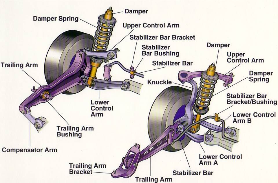
- Lower Control Arm (LCA): Connects the steering knuckle to the vehicle's frame or subframe. It allows the wheel to move up and down while maintaining its lateral position. A ball joint connects the LCA to the steering knuckle.
- Sway Bar (Stabilizer Bar): Connects the left and right sides of the suspension. It resists body roll during cornering, improving handling stability. The sway bar is connected to the suspension with end links.
- Steering Knuckle: Connects the suspension components to the wheel hub, allowing for steering.
Rear Suspension: Multi-Link Double Wishbone
The rear of the Civic EX Coupe uses a more sophisticated multi-link double wishbone suspension. This design offers superior handling and ride quality compared to simpler setups. It's more complex, though, so paying close attention to the diagram is essential.
- Upper and Lower Control Arms: Unlike the front, the rear has two separate control arms (upper and lower) on each side. This allows for more precise control over wheel movement and camber changes during suspension travel.
- Trailing Arm: Provides longitudinal stability and helps control wheel movement in the fore-aft direction.
- Shock Absorber (Damper): Similar to the front, it controls the compression and rebound of the spring. In the rear, it's typically separate from the spring.
- Coil Spring: Sits independently from the shock absorber, usually on a spring perch on the lower control arm.
- Sway Bar (Stabilizer Bar): Functions similarly to the front sway bar, reducing body roll.
- Hub Assembly: Where the wheel is mounted.
Key Specs: It's difficult to provide precise specifications without knowing the exact build and options on your specific vehicle. Important specs to look up in your service manual include:
- Spring Rates (Front and Rear): Affects ride comfort and handling.
- Shock Absorber Damping Coefficients: Dictates how quickly the shocks respond to movement.
- Ride Height: Distance from the ground to specific points on the chassis, which is crucial for proper alignment.
- Alignment Angles (Camber, Caster, Toe): Critical for tire wear and handling performance.
Understanding the Diagram's Symbols
Suspension diagrams use standard symbols to represent components and their connections. Here's a general guide:
- Solid Lines: Typically represent rigid components, such as control arms, struts, and sway bars.
- Dashed Lines: Can indicate hidden components or movement paths. For example, the path a control arm takes as the suspension compresses.
- Circles/Dots: Represent pivot points or joints, such as ball joints and bushings.
- Spring Symbols: A coiled line representing the coil spring. The number of coils and their spacing can sometimes (but not always) indicate the spring rate.
- Shock Absorber Symbols: A cylinder with a piston rod extending from it.
- Color Coding: While not always present, color coding might be used to differentiate between different systems or materials. For example, blue might represent hydraulic lines.
- Arrows: Indicate the direction of movement or force.
Important Note: Always refer to the diagram's legend or key for specific symbol interpretations. Different diagrams may use slightly different conventions.
How the Suspension Works
The 2008 Civic EX Coupe's suspension works by absorbing energy from road irregularities and isolating the chassis (and you!) from those vibrations. Here's a simplified explanation:
- Impact: When a wheel encounters a bump, the suspension compresses.
- Spring Action: The coil spring compresses, storing the energy from the impact.
- Damping: The shock absorber restricts the spring's compression and rebound, preventing excessive bouncing. It converts the kinetic energy into heat, which is then dissipated.
- Control Arm Movement: The control arms (both front and rear) allow the wheel to move vertically while maintaining its lateral position and controlling wheel geometry. In the rear, the multi-link design provides even greater control over wheel movement.
- Sway Bar Action: During cornering, the sway bar resists body roll by transferring force from the outside wheel (which is compressing) to the inside wheel (which is extending).
The interplay between these components determines the vehicle's ride quality, handling, and stability. A well-tuned suspension provides a comfortable ride while maintaining precise control.
Real-World Use: Basic Troubleshooting Tips
Here are some common suspension problems and how the diagram can help you troubleshoot:
- Clunking Noises: Often caused by worn-out bushings, ball joints, or sway bar end links. The diagram helps you locate these components and visually inspect them for wear or damage.
- Bouncing or Floating Sensation: Indicates worn-out shock absorbers. The diagram shows you how to access and replace them.
- Uneven Tire Wear: Could be caused by misaligned wheels, bent suspension components, or worn ball joints. The diagram helps you understand how different components affect wheel alignment.
- Poor Handling: Can be caused by a variety of issues, including worn-out components, improper alignment, or damaged sway bar links. The diagram helps you systematically check each component.
Example: If you hear a clunking noise when going over bumps, start by inspecting the sway bar end links using the diagram to locate them. If they are loose or damaged, replace them. If the noise persists, move on to the bushings and ball joints in the control arms.
Safety Considerations
Working on suspension components can be dangerous. Here are some key safety precautions:
- Spring Compression: Coil springs store a tremendous amount of energy. Improperly compressing or disassembling a strut assembly can result in serious injury or death. Always use a proper spring compressor and follow the manufacturer's instructions carefully. If you're not comfortable with this, take the strut assembly to a qualified mechanic.
- Vehicle Support: Never work under a vehicle supported only by a jack. Use jack stands rated for the vehicle's weight.
- Brake Lines: Be careful not to damage brake lines when working on suspension components. Damage to a brake line can result in brake failure.
- Torque Specifications: Always tighten bolts and nuts to the specified torque values. Overtightening can damage components, while undertightening can lead to failure. Consult your service manual for the correct torque specifications.
- Wheel Alignment: After replacing suspension components, it's crucial to have the wheels aligned by a qualified technician. This will ensure proper handling and prevent uneven tire wear.
WARNING: Working on suspension systems involves inherent risks. If you are not comfortable performing these repairs, consult a qualified mechanic.
We have a high-resolution diagram of the 2008 Honda Civic EX Coupe suspension system available for download. Having this resource handy while you're working on your car will greatly improve your understanding and accuracy. You can access it by clicking the link below [link to download]. Good luck, and remember to work safely!