
Honda Ignition Switch Wiring Color Code
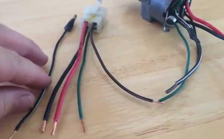
Understanding your Honda's ignition switch wiring is crucial for various reasons, from basic repairs like replacing a faulty switch to more advanced modifications like adding aftermarket security systems or remote starters. A solid grasp of the wiring color codes allows you to diagnose problems accurately, make safe connections, and avoid costly mistakes. This article will provide an in-depth look at the Honda ignition switch wiring color code, empowering you with the knowledge to confidently tackle related projects.
Why This Diagram Matters
The ignition switch is the gateway to your Honda's electrical system. It controls the flow of power to essential components, enabling you to start the engine, power accessories, and keep the car running. A faulty ignition switch or improperly wired connections can lead to a range of issues, including:
- No-start condition
- Accessory malfunctions (radio, lights, wipers)
- Battery drain
- Engine stalling
- Potential fire hazards
Having a clear understanding of the wiring allows for accurate diagnosis and repair. When adding aftermarket accessories like alarms or remote starters, you must correctly identify the wires for power, ignition, and starter to avoid damaging the vehicle's electrical system or creating safety risks. This knowledge also proves invaluable when tracing shorts or other electrical problems within the ignition circuit.
Key Specs and Main Parts of a Honda Ignition System
The Honda ignition system, like most modern automotive systems, utilizes a series of circuits activated by the ignition switch. Here are some of the key components:
- Ignition Switch: The central control point. This mechanical/electrical switch allows the driver to select different modes (Lock, Accessory, On/Run, Start).
- Battery: Provides the primary source of electrical power (typically 12V DC).
- Starter Motor: Cranks the engine to initiate combustion.
- Solenoid: An electromagnetic switch that engages the starter motor.
- Ignition Coil(s): Increases the battery voltage to create the spark needed to ignite the fuel-air mixture.
- ECU (Engine Control Unit): The "brain" of the engine, controlling various aspects of engine operation, including ignition timing.
- Fuses and Relays: Protection devices that prevent damage from overloads and control high-current circuits, respectively.
Understanding the function of each component helps you trace the flow of current and troubleshoot issues more effectively.
Deciphering the Wiring Diagram: Symbols, Colors, and Lines
Wiring diagrams use standardized symbols and color codes to represent electrical components and connections. Let's break down the key elements:
Symbols:
- Lines: Represent wires. Thicker lines often indicate higher current-carrying capacity.
- Circles: May represent connectors or splices.
- Rectangles: Often represent components like relays or the ECU. Internal lines within the rectangle show the components connections.
- Zigzag Lines: Typically represent resistors.
- Ground Symbol: (Usually a series of descending horizontal lines) indicates a connection to the vehicle's chassis ground. This is the return path for electrical current.
- Battery Symbol: (Parallel long and short lines) Represents the battery.
Color Codes:
Honda, like most manufacturers, uses a standard color-coding system for wires. Here are some common colors and their typical functions:
- Red (R): Usually indicates a direct connection to the battery (+12V).
- White (W): Often used for ground wires.
- Black (B): Typically also used for ground wires, sometimes interchangeable with White.
- Yellow (Y): Often used for switched power, particularly for accessories.
- Blue (L): Frequently used for lighting circuits.
- Green (G): Often used for signals from sensors.
- Brown (Br): Can sometimes be used for lighting or accessories.
Important Note: While these are common conventions, always refer to the specific wiring diagram for your Honda model and year. Color codes can vary slightly.
Understanding the Lines:
The lines in the diagram represent the wires themselves. Sometimes, you'll see numbers or letters alongside the lines. These may indicate:
- Wire Gauge: The thickness of the wire (e.g., 16 AWG).
- Circuit Number: A unique identifier for the circuit.
- Destination: A code indicating where the wire connects to (e.g., ECU Pin 22).
How the Honda Ignition Switch Works
The ignition switch is essentially a multi-pole, multi-throw switch. It has different positions that activate different circuits.
- Lock: No circuits are active. The steering wheel is often locked in this position.
- Accessory (ACC): Powers accessories like the radio and cigarette lighter without starting the engine.
- On/Run: Powers the ignition system, fuel pump, and other essential components for engine operation.
- Start: Activates the starter motor to crank the engine. This position is spring-loaded and returns to the "On/Run" position when released.
Internally, the switch has contacts that connect different wires depending on the selected position. For example, in the "Start" position, the Red wire (battery) connects to both the "On/Run" wire (powering the ignition system) and the wire leading to the starter solenoid. When the key is released and returns to the "On/Run" position, the connection to the starter solenoid is broken, and the starter disengages.
Real-World Use: Basic Troubleshooting
Here are some basic troubleshooting tips using your knowledge of the wiring diagram:
- No-Start Condition: Use a multimeter to check for voltage at the "Start" wire when the key is in the "Start" position. If there's no voltage, the switch itself might be faulty or there might be a break in the wire.
- Accessory Malfunction: Check for voltage at the "ACC" wire when the key is in the "ACC" position. If there's no voltage, the switch, the wire, or the accessory fuse could be the culprit.
- Battery Drain: A faulty ignition switch can sometimes cause a parasitic battery drain. Disconnecting the switch and monitoring the battery voltage can help determine if the switch is the source of the drain.
Always use a multimeter to test for voltage and continuity. Never rely solely on visual inspection.
Safety Precautions
Working with automotive electrical systems can be dangerous. Take the following precautions:
- Disconnect the Battery: Before working on any electrical component, disconnect the negative terminal of the battery to prevent shorts and shocks.
- Use Proper Tools: Use insulated tools and wear appropriate safety gear, such as safety glasses.
- Avoid Water: Never work on electrical systems in wet conditions.
- Identify Airbag Circuits: Be extremely cautious when working near airbag circuits. Accidental activation of an airbag can cause serious injury. Disconnecting the battery is a must and waiting several minutes is a good idea to deplete any residual charge.
- High Current Components: The wires connected to the starter solenoid and alternator carry high current. Avoid touching these wires while the engine is running or being cranked.
The ignition switch itself typically operates on 12V DC, but the circuits it controls can power high-voltage components like the ignition coils. Treat all electrical components with respect.
Disclaimer: This article provides general information. Always consult the specific wiring diagram for your Honda model and year. If you are not comfortable working with electrical systems, seek the assistance of a qualified mechanic.
We have a comprehensive collection of Honda wiring diagrams available. Contact us to request the specific diagram for your Honda model year.