Honda Ignition Switch Wiring Diagram
Understanding the Honda ignition switch wiring diagram is crucial for a variety of automotive tasks, ranging from diagnosing starting issues to performing aftermarket modifications. This document serves as your guide to deciphering these diagrams, empowering you to tackle electrical repairs and enhancements with confidence. Whether you're wrestling with a no-start condition, adding a remote starter, or simply aiming to deepen your understanding of automotive electrical systems, this knowledge is invaluable.
Purpose of the Ignition Switch Wiring Diagram
The ignition switch wiring diagram is essentially a roadmap for the electrical circuits associated with the ignition switch. It illustrates how the switch connects to other components, such as the battery, starter motor, fuel pump, and various control modules. It allows you to:
- Diagnose starting problems: By tracing circuits, you can identify faulty components or wiring causing a no-start or intermittent starting condition.
- Install aftermarket accessories: Adding remote starters, alarms, or other electrical devices requires understanding which wires carry power during different ignition switch positions.
- Perform electrical repairs: If a wire is damaged or a connector is corroded, the diagram helps you identify the correct replacement wire and its proper connection point.
- Gain a deeper understanding of the electrical system: Studying the diagram allows you to grasp the relationships between different components and how they work together to start and run the vehicle.
Key Specs and Main Parts
While specific wiring configurations vary between Honda models and model years, certain common elements are found in most ignition switch circuits. Key components include:
- Battery (BAT): Provides the initial power source for the entire system. The battery connection is usually a heavy-gauge wire, often red, carrying a substantial amount of current.
- Ignition Switch: The mechanical switch controlled by the key. It has multiple positions (LOCK, ACC, ON, START) that activate different circuits.
- Starter Motor (STRT): Cranks the engine, initiating the combustion process. The starter circuit typically uses a high-current relay, sometimes labeled "STA" or "STR".
- Accessory Circuit (ACC): Powers accessories like the radio, climate control, and power windows when the key is in the ACC or ON position.
- Ignition Circuit (IGN): Supplies power to the ignition system (spark plugs, coils) and fuel injection system when the key is in the ON or START position. This circuit is crucial for the engine to run.
- Ground (GND): Provides a return path for the electrical current, completing the circuit. Grounds are typically connected to the vehicle's chassis.
- Fuses and Relays: Protect the circuits from overloads and control high-current devices. Fuses are represented by a specific symbol. Relays use a coil symbol and a switch symbol.
Key specifications to note on the diagram include wire gauge (thickness), which indicates the wire's current-carrying capacity, and voltage levels (typically 12V for automotive systems). These specs are important when troubleshooting and replacing wires.
Understanding Symbols on the Diagram
Interpreting the symbols and notations on the wiring diagram is essential. Here's a breakdown of common elements:
- Lines: Represent wires. Different line thicknesses can indicate wire gauge. Dashed lines may represent wires located within a harness or connectors.
- Colors: Wires are color-coded (e.g., RED, BLU, GRN, YEL, BLK). The diagram will have a color code chart. Knowing the wire color is extremely helpful for identification within the vehicle.
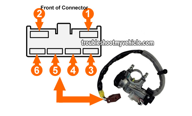
- Connectors: Represented by circles, squares, or specialized symbols showing how wires are joined. Connector numbers are often included for easy identification.
- Ground Symbols: Represent the chassis ground connection. Several different ground symbols exist, but they all indicate a connection to the vehicle's metal frame.
- Component Symbols: Each component (switch, relay, fuse, etc.) has its own unique symbol. A legend on the diagram will define these symbols.
- Numerical Designations: Wires are often labeled with numbers or alphanumeric codes that correspond to the wiring harness and connector locations.
It's important to remember that wiring diagrams are often simplified representations of the actual wiring harness. The physical layout of wires in the vehicle may differ from the diagram.
How It Works: The Ignition Sequence
The ignition switch orchestrates a sequence of events to start and run the engine. Let's trace the typical flow of electricity through the various switch positions:
- LOCK: No circuits are active, and the steering wheel is locked.
- ACC (Accessory): Power is supplied to accessories like the radio, climate control, and power windows. The IGN and STRT circuits remain inactive. The ACC circuit bypasses the ignition system, providing power only to convenience features.
- ON (Run): Power is supplied to the ignition system (spark plugs, coils), fuel injection system, and all accessories. The engine control unit (ECU) is powered up and begins monitoring sensors. The fuel pump primes, and the vehicle is ready to start. The ignition circuit is active at this point.
- START: Power is supplied to the starter motor, which cranks the engine. Simultaneously, the ignition system and fuel injection system continue to receive power. Once the engine starts, the key is released back to the ON position. The starter relay is energized in this position.
Internally, the ignition switch uses a series of contacts that open and close as the key is rotated, connecting different circuits to the battery. The wiring diagram illustrates these internal connections.
Real-World Use: Basic Troubleshooting
Using the ignition switch wiring diagram for troubleshooting can save time and money. Here are some basic tips:
- No-Start Condition: Use a multimeter to check for voltage at the battery, the ignition switch, and the starter motor. Compare your readings to the wiring diagram to identify any breaks in the circuit. Start by checking the fuses related to the ignition and starter systems.
- Accessory Issues: If accessories are not working, check the ACC circuit fuse and the ignition switch itself. Use the wiring diagram to trace the power flow to the affected accessories.
- Intermittent Starting: Inspect the ignition switch connector for corrosion or loose wires. Check the starter relay for proper operation. The diagram will show you the locations of the various connectors and relays in the system.
- Wiring Modifications: Before making any wiring modifications, consult the diagram to identify the correct wires and their functions. Always use properly rated wire and connectors.
Safety Considerations
Working with automotive electrical systems can be dangerous. Always disconnect the negative battery cable before working on any electrical components. The ignition switch wiring often involves high-current circuits, particularly the starter motor circuit. Be extremely cautious when working around these circuits. Never short-circuit wires or connect them to the wrong terminals. The battery provides a very high current and can easily cause fires or explosions. Before disconnecting any components, ensure that the key is in the LOCK position.
When dealing with airbag systems, always follow the manufacturer's recommended procedures for disabling the system before working on any related wiring. Incorrectly handling airbag circuits can result in accidental airbag deployment, causing serious injury.
Remember, working on automotive electrical systems requires a basic understanding of electrical principles and safety precautions. If you are not comfortable performing these tasks, consult a qualified mechanic.
We have a sample Honda ignition switch wiring diagram file available for download. This diagram covers a common Honda model and will provide a practical example of the concepts discussed in this article. You can download it here.