
Honda Motorcycle Starter Solenoid Wiring Diagram
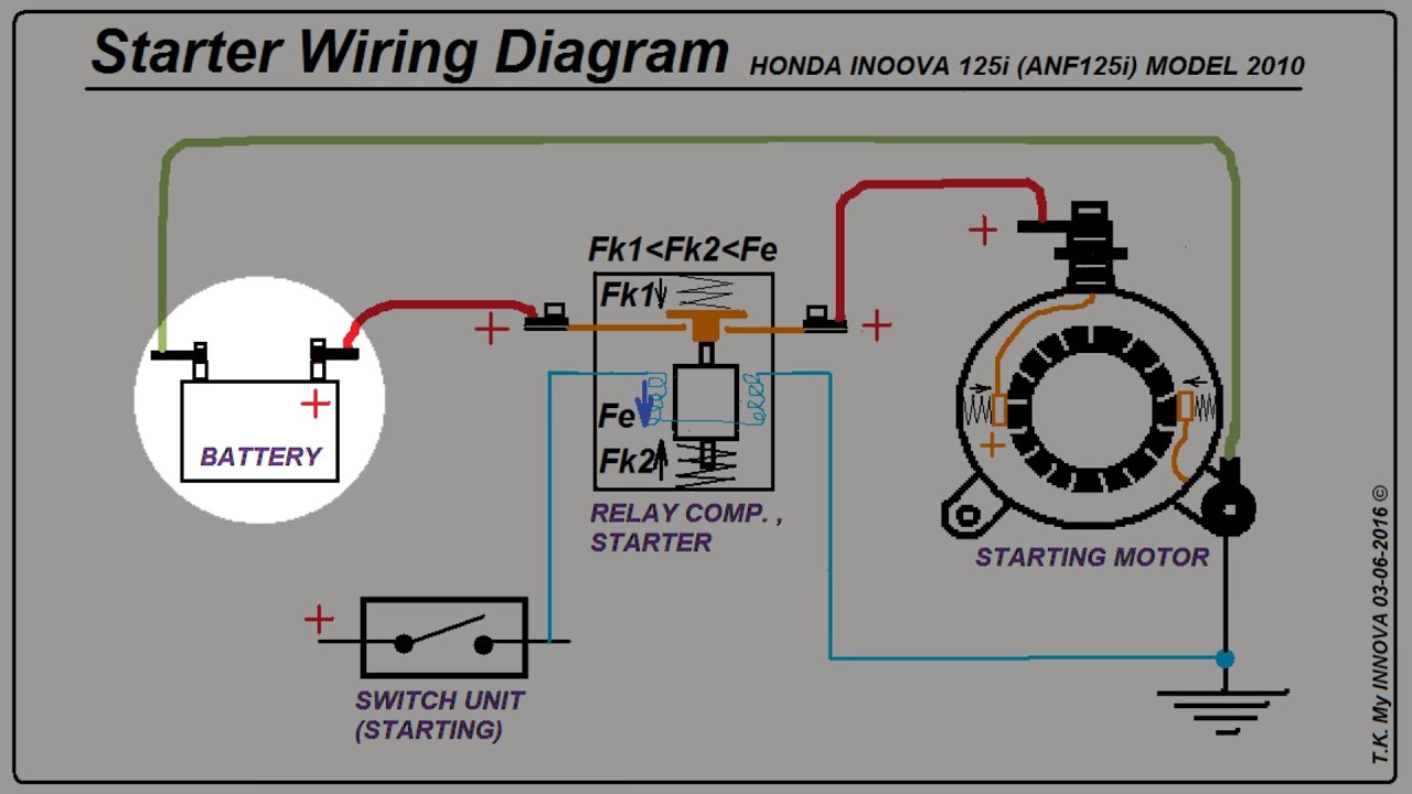
Let's dive into the world of Honda motorcycle starter solenoid wiring diagrams. Understanding this diagram is crucial whether you're troubleshooting a no-start issue, performing modifications, or simply expanding your knowledge of motorcycle electrical systems. Think of this as your roadmap to diagnosing and repairing starting problems – a skill that can save you money and time. We're going to cover everything from the diagram's purpose to real-world troubleshooting, presented in a way that's accessible to experienced DIYers like yourself.
Why Bother with a Wiring Diagram?
The starter solenoid wiring diagram is more than just a piece of paper; it's the key to understanding how your motorcycle's starting system functions. Here’s why it's so important:
- Troubleshooting: When your bike won't start, the diagram helps you trace the electrical path to pinpoint the faulty component – whether it's the battery, solenoid, starter motor, or associated wiring.
- Repair: Once you've identified the problem, the diagram guides you through the repair process, ensuring you reconnect everything correctly.
- Modification: Planning to add a new accessory like an aftermarket alarm or remote starter? The diagram helps you understand the existing wiring so you can integrate your new components safely and effectively.
- Knowledge: Even if your bike is running perfectly, studying the diagram will give you a deeper understanding of your motorcycle's electrical system, making you a more confident and capable mechanic.
Key Specs and Main Parts
Before we dive into the diagram itself, let's review the main components and their roles:
- Battery: The heart of the electrical system, providing the initial power to start the engine. Typically, a 12-volt DC system.
- Ignition Switch: This switch activates the entire electrical system, including the starting circuit.
- Starter Button (or Switch): This is the switch that, when pressed, signals the solenoid to engage.
- Starter Solenoid: A high-current switch that connects the battery directly to the starter motor. Essentially, it's a relay designed to handle the high amperage needed by the starter motor. The solenoid has two main circuits:
- Control Circuit: A low-current circuit that activates the solenoid's internal electromagnet.
- High-Current Circuit: The heavy-gauge wiring that carries the large current from the battery to the starter motor.
- Starter Motor: An electric motor that spins the engine's crankshaft, initiating the combustion process.
- Fuses: Protect the electrical system from overloads. The starter circuit usually has a high-amperage fuse.
- Ground Connections: Provide a return path for the electrical current back to the battery. Clean, tight ground connections are crucial for proper operation.
Decoding the Wiring Diagram: Symbols, Lines, and Colors
Wiring diagrams use standardized symbols and conventions to represent electrical components and connections. Understanding these is key to interpreting the diagram:
- Lines: Represent wires. Thicker lines usually indicate wires carrying higher current.
- Colors: Each wire is typically identified by a color code (e.g., Blue/Yellow, Green, Black). This color coding helps you trace wires within the harness. Refer to the diagram's legend for the specific color codes used on your Honda model.
- Symbols:
- Battery: Represented by a series of short and long parallel lines.
- Switch: Shown as a break in the line, with a symbol indicating the switch type (e.g., toggle, momentary).
- Solenoid: Often depicted as a coil with a switch connected to it.
- Starter Motor: Usually represented by a circle with an "M" inside.
- Fuse: A zig-zag line inside a rectangle or circle.
- Ground: Typically represented by a series of downward-pointing lines, resembling an upside-down tree.
- Numbers and Letters: May be used to identify specific connectors, terminals, or wire gauges.
Important: Always refer to the specific wiring diagram for your Honda motorcycle model. Wiring can vary significantly between models and even between production years of the same model. Using the wrong diagram can lead to misdiagnosis and incorrect repairs.
How the Starting System Works
Here's a simplified explanation of how the starting system functions, referencing the wiring diagram:
- When you turn the ignition switch to the "ON" position, power is supplied to various circuits, including the starter button circuit.
- Pressing the starter button (or switch) completes the control circuit to the starter solenoid. This low-current circuit energizes the solenoid's internal electromagnet.
- The energized electromagnet pulls a plunger inside the solenoid, which connects the high-current circuit between the battery and the starter motor.
- The battery's high current flows directly to the starter motor, causing it to spin the engine's crankshaft.
- Once the engine starts, you release the starter button, which de-energizes the solenoid, disconnecting the battery from the starter motor.
Real-World Use: Basic Troubleshooting Tips
Let's look at some common starting problems and how the wiring diagram can help:
- No Start, No Click:
- Check the battery voltage. A fully charged 12-volt battery should read around 12.6 volts.
- Inspect the fuses, especially the main fuse and the starter solenoid fuse.
- Use a multimeter to check for voltage at the starter button when pressed. If there's no voltage, the switch may be faulty or the wiring between the ignition switch and the starter button may be broken.
- No Start, Clicking Sound:
- This usually indicates a weak battery or a problem with the solenoid.
- Check the battery voltage under load (while trying to start the engine). If the voltage drops significantly, the battery is likely weak.
- Check the solenoid's connections for corrosion. Clean and tighten them.
- You can try bypassing the solenoid (with extreme caution - see safety section) to see if the starter motor spins. If it does, the solenoid is likely faulty.
- Starter Motor Spins But Engine Doesn't Crank:
- This suggests a problem with the starter motor's internal clutch (Bendix drive) or the engine's starter clutch. The wiring diagram won't directly help with this, as it's a mechanical issue, but it confirms the motor is getting power.
Safety First! Handle with Care
Working with electrical systems involves inherent risks. Here are some crucial safety precautions:
- Disconnect the Battery: Always disconnect the negative (-) battery terminal before working on the electrical system. This prevents accidental shorts and electrical shocks.
- Work in a Well-Ventilated Area: Batteries can produce hydrogen gas, which is flammable.
- Use Insulated Tools: Protect yourself from electric shock.
- Avoid Bypassing Safety Devices: Fuses are there for a reason. Don't bypass them unless you're absolutely sure you understand the risks.
- Caution When Bypassing the Solenoid: Bypassing the solenoid involves directly connecting the battery to the starter motor. This can create a large spark and potentially damage components if there's a short circuit. Wear eye protection and gloves, and be prepared for a sudden jolt. Only do this for a very brief test.
- Double-Check Your Work: Before reconnecting the battery, carefully review your wiring to ensure everything is connected correctly.
Remember, when in doubt, consult a qualified motorcycle mechanic. Working with electrical systems can be dangerous if you're not comfortable with the procedures.
Understanding your Honda motorcycle's starter solenoid wiring diagram empowers you to diagnose and repair starting issues effectively. By combining this knowledge with careful troubleshooting techniques and a strong emphasis on safety, you can tackle most common starting problems with confidence.
We have the file available for download. This diagram is specific to [Insert Year, Make and Model Here], but the principles described above apply to most Honda motorcycles.