
Honda Pressure Washer Carburetor Diagram
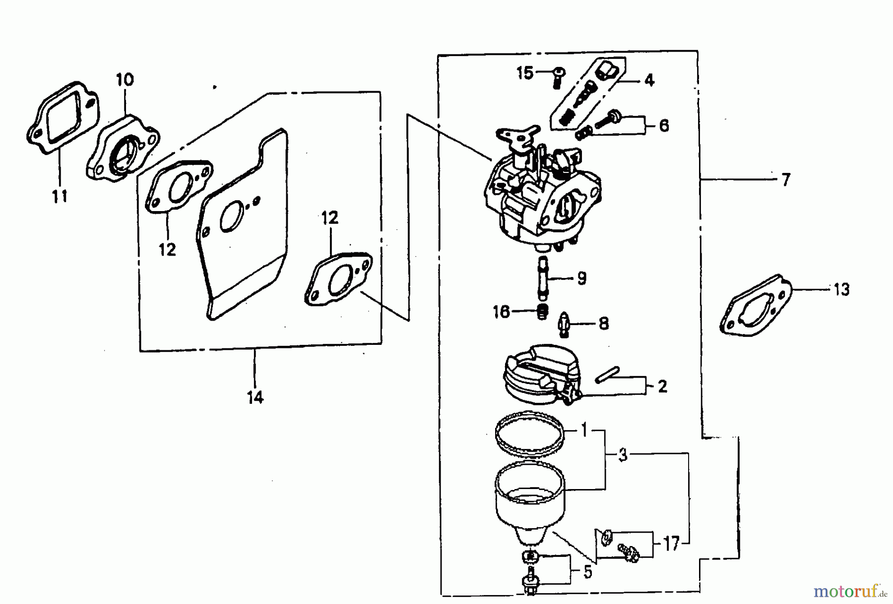
The carburetor, the heart of many small engines powering Honda pressure washers, is responsible for precisely mixing air and fuel to create a combustible mixture. While modern engines often utilize fuel injection, many reliable and widely used Honda pressure washers still rely on carburetors. Understanding its function and construction is paramount for effective maintenance, troubleshooting, and repair. This article delves into the intricacies of a Honda pressure washer carburetor diagram, offering insights that empower the experienced DIYer to confidently tackle carburetor-related issues.
Why a Carburetor Diagram Matters
A carburetor diagram serves as a visual roadmap, crucial for several reasons:
- Troubleshooting: When a pressure washer sputters, won't start, or runs poorly, the diagram helps pinpoint potential problem areas within the carburetor. Is a jet clogged? Is a gasket failing? The diagram helps you visualize where to look.
- Repair and Overhaul: Disassembling a carburetor without a guide can be a recipe for disaster. The diagram shows the correct order of component assembly, preventing errors and ensuring proper function.
- Parts Identification: Carburetors contain numerous small parts – jets, needles, springs, and gaskets. The diagram provides clear identification, facilitating accurate parts ordering and replacement.
- Understanding Engine Operation: Even if you don't plan on disassembling your carburetor, the diagram offers a valuable learning opportunity, showcasing the internal workings of your engine and how air and fuel mix. It can enhance your understanding of small engine theory and repair.
Key Specs and Main Parts
While specific carburetor designs vary slightly between Honda models (GX160, GX200, etc.), the fundamental principles remain consistent. Here are the key components you'll typically find labeled on a diagram:
- Float Bowl: This reservoir at the bottom of the carburetor stores fuel. A diagram will show the fuel inlet valve and how it regulates fuel flow into the bowl, maintaining a constant fuel level.
- Float: Typically made of plastic or brass, the float controls the fuel inlet valve. Its position determines how much fuel enters the bowl.
- Main Jet: This precisely sized orifice meters the amount of fuel delivered to the engine at higher throttle openings. The diagram will indicate its location within the carburetor body and how it interacts with the fuel stream.
- Pilot Jet (Idle Jet): This small jet controls fuel delivery at idle and low-speed operation. It's crucial for smooth starting and idling.
- Idle Mixture Screw: This adjustable screw fine-tunes the air-fuel mixture at idle, allowing you to optimize engine performance.
- Throttle Valve (Butterfly Valve): Controlled by the throttle lever, this valve regulates the amount of air entering the carburetor, directly affecting engine speed.
- Choke Valve: Used for cold starting, the choke valve restricts airflow, creating a richer fuel mixture.
- Venturi: This constricted section of the carburetor creates a pressure drop, drawing fuel from the jets into the air stream. The diagram will clearly show its shape and position within the carburetor bore.
- Emulsion Tube: This tube, located near the main jet, helps to atomize fuel by introducing air bubbles into the fuel stream.
- Gaskets and O-rings: These seals prevent air leaks, which can disrupt the air-fuel mixture and cause engine problems.
Decoding the Diagram: Symbols and Conventions
Carburetor diagrams employ standard symbols and conventions to represent components and flow paths. Understanding these is essential for accurate interpretation:
- Solid Lines: These typically represent fuel lines or passageways within the carburetor body. Thicker lines often indicate primary fuel pathways.
- Dashed Lines: These might represent air passages or vacuum lines.
- Arrows: Arrows indicate the direction of fuel or air flow. Pay close attention to these to understand how the air-fuel mixture is created.
- Cross-Sectional Views: Diagrams often use cross-sectional views to reveal the internal structure of the carburetor. These views show how components are positioned relative to each other.
- Exploded Views: Exploded views show all the carburetor parts separated and arranged in the order of assembly. This is extremely helpful during reassembly.
- Numbers and Letters: Components are usually labeled with numbers or letters, corresponding to a parts list included with the diagram.
How a Carburetor Works
The carburetor's operation relies on a fundamental principle of fluid dynamics: Bernoulli's principle. As air flows through the venturi, its velocity increases, and its pressure decreases. This pressure drop draws fuel from the float bowl, through the jets, and into the air stream. The amount of fuel delivered is controlled by the size of the jets and the position of the throttle valve.
Here's a simplified breakdown:
- Air enters the carburetor through the air filter and passes through the venturi.
- The pressure drop in the venturi draws fuel from the float bowl, metered by the main jet and pilot jet.
- The idle mixture screw fine-tunes the air-fuel mixture at idle.
- The throttle valve controls the amount of air entering the engine, regulating engine speed.
- The choke valve, when engaged, restricts airflow, enriching the fuel mixture for cold starts.
- The air-fuel mixture is drawn into the engine's cylinder, where it is ignited, powering the pressure washer.
Real-World Use: Basic Troubleshooting
A carburetor diagram becomes invaluable when troubleshooting common pressure washer problems. Here are a few examples:
- Engine won't start: Check the fuel supply to the carburetor. If fuel is present, examine the choke valve to ensure it's functioning correctly. The diagram can help you locate and inspect the pilot jet for clogs.
- Engine runs rough or sputters: This could indicate a clogged main jet or an air leak around the carburetor. The diagram helps you identify potential leak points, such as gaskets and O-rings.
- Engine idles poorly: Adjust the idle mixture screw according to the diagram's instructions. If adjustment doesn't solve the problem, the pilot jet may be clogged.
- Fuel leaking from carburetor: Inspect the float bowl, float, and fuel inlet valve. The diagram will show their relationship and help you identify the source of the leak. Often, a stuck float or a damaged float needle valve is the culprit.
Before attempting any carburetor repair, ensure the engine is cool and the fuel tank is empty.
Safety Considerations
Working with carburetors involves handling flammable fuel. Exercise extreme caution and observe the following safety precautions:
- Work in a well-ventilated area: Fuel vapors are harmful and can be explosive.
- Avoid open flames or sparks: Fuel is highly flammable. Keep all ignition sources away from the work area.
- Wear safety glasses: Protect your eyes from fuel splashes.
- Dispose of fuel properly: Do not pour fuel down drains or onto the ground.
- Be especially careful with the float bowl: Disconnecting the fuel line from a full float bowl can result in fuel spillage. Have a container ready to catch any fuel that may leak.
- Understand the float needle valve. It can be sharp, handle with care.
Remember, some carburetor components, like the jets, are very small and easily lost. Work on a clean, well-lit surface to prevent losing them. Furthermore, be mindful of the springs and their orientation during disassembly to guarantee proper reassembly.
By understanding the principles outlined in this article and referring to a detailed carburetor diagram, you can confidently troubleshoot and repair your Honda pressure washer's carburetor, extending its lifespan and saving on costly repair bills. We have access to a detailed Honda Pressure Washer Carburetor Diagram. Contact us to request the file.