Hopkins 7 Pin Trailer Wiring Diagram
So, you're ready to dive into the world of trailer wiring? Excellent! Knowing your way around a Hopkins 7-Pin trailer wiring diagram is crucial for anyone who hauls trailers, whether it's for work, recreation, or anything in between. This guide isn't just about understanding the diagram itself; it's about equipping you with the knowledge to troubleshoot issues, perform repairs, and even upgrade your trailer wiring system confidently. We’ll cover the essential elements of the diagram, the purpose it serves, and how it translates to real-world applications. And the best part? We have a full high-resolution version of the diagram ready for you to download and keep for future reference.
Purpose of the 7-Pin Trailer Wiring Diagram
Why bother with a diagram at all? Well, imagine trying to assemble a complex piece of furniture without instructions. That's what working on trailer wiring without a diagram is like – a recipe for frustration and potentially dangerous errors. The 7-pin trailer wiring diagram serves several key purposes:
- Repair and Maintenance: When a trailer light stops working, or your electric brakes fail, the diagram helps you trace the fault and pinpoint the problem component quickly.
- Installation and Upgrades: Whether you're installing a new trailer brake controller or adding auxiliary lights, the diagram ensures you connect everything correctly and avoid short circuits.
- Understanding the System: Even if everything is working perfectly, studying the diagram allows you to understand how the different components of your trailer's electrical system interact. This knowledge is invaluable for preventative maintenance and identifying potential problems before they escalate.
- Ensuring Compliance: Correct wiring is essential for road safety and legal compliance. A faulty electrical system can lead to accidents and fines. The diagram helps you meet the required standards.
Key Specs and Main Parts in a 7-Pin Connector
The 7-pin connector, also known as an RV blade connector, is the most common type for trailers requiring electric brakes and auxiliary power. The "7 pins" refer to the seven individual contacts within the connector, each dedicated to a specific function. The standard arrangement allows for essential functions plus added safety and convenience features.
Here's a breakdown of each pin and its standard function:
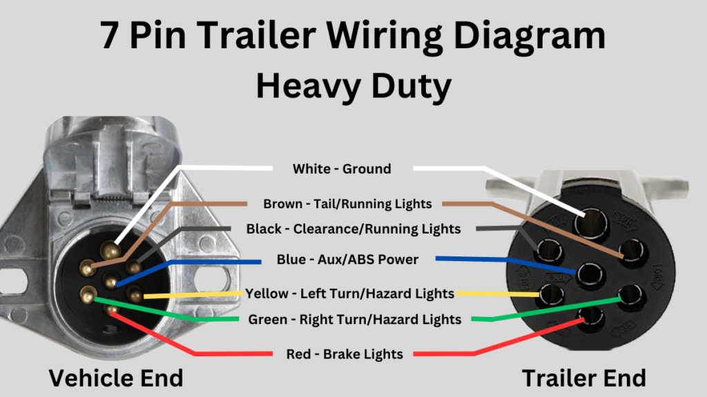
- Pin 1: Ground (White Wire): This is the foundation of the entire electrical system. It provides a return path for current flow and is essential for all circuits to function correctly. Poor grounding is a common cause of trailer wiring problems. A solid ground connection to the trailer frame is essential.
- Pin 2: Tail Lights (Brown Wire): Powers the trailer's tail lights, ensuring visibility at night and in low-light conditions.
- Pin 3: Left Turn/Stop Light (Yellow Wire): Controls the left turn signal and stop light on the trailer.
- Pin 4: Right Turn/Stop Light (Green Wire): Controls the right turn signal and stop light on the trailer.
- Pin 5: Electric Brakes (Blue Wire): Activates the trailer's electric brakes, synchronized with the tow vehicle's brakes. This requires a brake controller in the tow vehicle. This is critical for safe towing of heavier trailers.
- Pin 6: 12V Auxiliary Power (Red or Black Wire): Provides a constant 12V power supply to the trailer. This can be used to charge trailer batteries, power interior lights, or operate other electrical appliances. It is sometimes referred to as “Auxiliary” or “Battery Charge.”
- Pin 7: Reverse Lights (Black or Violet Wire): Activates the trailer's reverse lights when the tow vehicle is in reverse.
The specifications for wiring typically include the gauge (thickness) of the wire used for each function. The gauge is essential for providing enough current carrying capacity. For example, the electric brake wire (blue) usually needs to be a heavier gauge than the tail light wire (brown) because the electric brakes draw a significant amount of current. Always consult your trailer's specifications or a qualified electrician when replacing wiring.
Understanding the Symbols
Trailer wiring diagrams use standard electrical symbols to represent components and connections. Here's a brief overview of some common symbols you'll encounter:
- Solid Lines: Represent wires or conductors. The thickness of the line doesn't necessarily indicate the wire gauge.
- Dashed Lines: Often indicate connections that are made through a switch or relay. These show the potential connections, not always the actual connections at a given time.
- Circles with Numbers: Indicate the pin number on the connector. These are essential for correctly identifying the function of each wire.
- Ground Symbol (Three Horizontal Lines): Represents a connection to the vehicle or trailer frame, providing a ground path.
- Light Bulb Symbol: Represents a light fixture, such as a tail light, turn signal, or brake light.
- Rectangles or Squares: May represent relays, fuses, or other electrical components.
Color codes are also crucial. While wire colors may vary slightly depending on the manufacturer, the standard colors mentioned above are commonly used. Using the correct wire colors simplifies troubleshooting and ensures that future repairs are performed correctly. It is a very bad idea to mix up the colors when wiring.
How It Works: The Circuit
The 7-pin wiring system is essentially a series of electrical circuits. Each circuit begins at the tow vehicle's electrical system, travels through the appropriate pin on the connector, powers a specific function on the trailer, and then returns to the tow vehicle through the ground wire. Let's break down a simple circuit, like the tail lights:
- The tow vehicle's tail light circuit is activated when the headlights are turned on.
- Current flows from the tow vehicle, through the brown wire, to pin 2 on the 7-pin connector.
- The current travels along the brown wire on the trailer to the trailer's tail lights, illuminating them.
- The current returns to the tow vehicle through the white ground wire, completing the circuit.
The other circuits function in a similar way, with each pin and wire dedicated to a specific function. The brake controller, in the tow vehicle, sends a signal to the electric brakes through the blue wire when the tow vehicle's brakes are applied. The auxiliary power circuit provides a constant 12V supply through the red (or black) wire, which can be used to charge a trailer battery or power other electrical components.
Real-World Use: Basic Troubleshooting
Here are some basic troubleshooting tips using the 7-pin wiring diagram:
- No Lights at All: Start by checking the ground connection. A poor ground is the most common cause of complete electrical failure. Also, check the tow vehicle's fuses related to trailer wiring.
- One Light Not Working: Use a multimeter to check for voltage at the light fixture. If there's no voltage, trace the wire back to the connector, checking for breaks or loose connections along the way.
- Brakes Not Working: Check the brake controller in the tow vehicle. Ensure it's properly adjusted and sending a signal when the brakes are applied. Use a multimeter to check for voltage at the blue wire on the trailer connector. Then, inspect the brake magnets on the trailer axles.
- Fuses Blowing: A blown fuse indicates a short circuit. Inspect the wiring for damaged insulation or exposed wires that may be touching the frame. A common place to find shorts is near the axles, where wires can rub against the suspension components.
Remember to always disconnect the trailer from the tow vehicle's electrical system before performing any repairs. Use a circuit tester or multimeter to check for voltage and continuity. A test light, which uses a simple bulb to indicate the presence of voltage, can be a useful tool.
Safety First
Working with electricity always carries risks. Here are some safety precautions to keep in mind:
- Disconnect Power: Always disconnect the trailer from the tow vehicle's electrical system before working on the wiring.
- Use Proper Tools: Use insulated tools designed for electrical work.
- Wear Safety Glasses: Protect your eyes from sparks and debris.
- Be Aware of the Battery: The trailer battery can store a significant amount of energy. Avoid short circuits, which can cause sparks, fires, and even explosions.
- High-Current Components: Be extra cautious when working with the electric brake and auxiliary power circuits, as these circuits carry high current.
If you are uncomfortable working with electricity or are unsure about any aspect of the wiring, consult a qualified electrician or trailer repair technician. Safety should always be your top priority.
Get Your Diagram!
With this knowledge, you are better equipped to tackle common trailer wiring tasks. Now you have a much better understanding of the Hopkins 7-Pin trailer wiring system. But what about having a diagram on hand when you're out in the field? We have the complete, high-resolution Hopkins 7-Pin trailer wiring diagram that you can download and save for future reference. With it, you'll be able to confidently diagnose and repair trailer wiring issues.