
Hopkins Trailer Connector Wiring Diagram
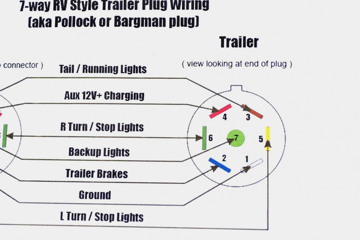
So, you're looking to get your hands dirty with trailer wiring? Smart move! Understanding the Hopkins trailer connector wiring diagram is crucial whether you're troubleshooting a faulty connection, upgrading your lighting, or even building a trailer from scratch. It's not rocket science, but it does require a bit of know-how. This article will break down the diagram, explaining the purpose, components, and how to use it in real-world scenarios.
Purpose of the Hopkins Trailer Connector Wiring Diagram
Why bother with a wiring diagram? Simple: accuracy and safety. Trying to guess which wire goes where is a recipe for disaster. You could end up with flickering lights, blown fuses, or even damage to your vehicle's electrical system. The diagram provides a clear, standardized visual representation of how each wire in the Hopkins connector should be connected to the corresponding function on your trailer.
Specifically, a Hopkins trailer connector wiring diagram helps you to:
- Troubleshoot existing wiring problems: Identify breaks, shorts, or incorrect connections.
- Install a new trailer connector correctly, ensuring all lights and brakes function properly.
- Customize your trailer wiring: Adapt the wiring for specific needs, such as adding auxiliary lights or a charging circuit.
- Understand the electrical system: Gain a deeper understanding of how your trailer's electrical system interacts with your tow vehicle.
Key Specs and Main Parts of the Hopkins Connector
Hopkins is a popular brand, and their connectors come in several configurations, but the most common are the 4-way flat, 5-way flat, 6-way round, and 7-way round (or RV-style) connectors. Each configuration supports a different set of functions. The 4-way flat connector is the simplest, handling basic lighting: running lights, brake lights, and turn signals. The 7-way connector, on the other hand, supports all of that, plus a 12V power supply, electric brake control, and reverse lights.
Here's a breakdown of the typical functions each connector supports:
- 4-Way Flat: Ground, Tail Lights, Left Turn/Brake, Right Turn/Brake.
- 5-Way Flat: Adds a wire for hydraulic brakes. (Less common now with electric brakes being standard.)
- 6-Way Round: Typically found on older trailers, includes ground, tail lights, left turn/brake, right turn/brake, electric brake, and auxiliary power.
- 7-Way Round (RV): Ground, Tail Lights, Left Turn/Brake, Right Turn/Brake, Electric Brake, 12V Auxiliary Power, and Reverse Lights.
The key specs you'll want to know relate to the wire gauge (thickness) and the amperage rating of the circuit. Generally, 16-gauge wire is sufficient for lighting circuits, while thicker 12- or 10-gauge wire is needed for electric brakes and auxiliary power. Exceeding the amperage rating of the wire can lead to overheating and fire, so always check your trailer and vehicle manuals for the recommended wire gauge.
Understanding the Symbols: Lines, Colors, and Icons
A Hopkins trailer connector wiring diagram isn't just a jumble of lines and colors; it's a carefully crafted representation of the electrical circuit. Let's break down the key elements:
- Lines: Represent wires. The thickness of the line may or may not indicate the wire gauge, so always double-check the wire markings.
- Colors: Each color corresponds to a specific function. The color code is fairly standardized, but there can be slight variations between manufacturers. Here's a common color scheme:
- White: Ground
- Brown: Tail/Running Lights
- Yellow: Left Turn/Brake
- Green: Right Turn/Brake
- Blue: Electric Brake
- Red: Stop Lamps (May sometimes be combined with turn signals)
- Black: 12V Auxiliary Power (Battery Charge)
- Purple: Reverse Lights
- Icons: These represent electrical components like lights, switches, and connectors. A simple circle with an "X" is often used to denote a light bulb. More complex diagrams may use schematic symbols for diodes, resistors, and other components.
A typical diagram will show the connector's pins or sockets, with lines connecting them to the corresponding functions. Pay close attention to the pin numbering or lettering on the connector itself, as this is crucial for making the correct connections.
How It Works: Following the Circuit
The wiring diagram is a roadmap for the electrical circuit. It shows how power flows from the tow vehicle to the trailer and back. The ground wire (typically white) provides a return path for the current, completing the circuit. When you activate a turn signal in your vehicle, for example, the corresponding wire in the trailer connector receives power, which then energizes the turn signal bulb on the trailer. Similarly, when you press the brake pedal, power flows through the brake light wire to activate the brake lights on the trailer. For electric brakes, the brake controller in the tow vehicle sends a signal through the blue wire to activate the trailer's brakes.
The 12V auxiliary power wire (black) provides a constant source of power to the trailer, which can be used to charge a battery or power other accessories. It's important to note that this wire is often protected by a fuse in the tow vehicle.
Real-World Use: Basic Troubleshooting Tips
Here are some common troubleshooting scenarios and how the wiring diagram can help:
- No Lights: Check the ground connection first! A poor ground is the most common cause of lighting problems. Use the diagram to verify that the ground wire is securely connected to both the tow vehicle and the trailer frame.
- Flickering Lights: This can be caused by loose connections, corrosion, or damaged wires. Use the diagram to trace the circuit and inspect each connection.
- One Light Not Working: Use the diagram to identify the specific wire for that light and check for breaks or shorts. Also, check the bulb itself.
- Brakes Not Working: Verify that the brake controller in the tow vehicle is properly configured and sending a signal. Use the diagram to check the blue wire for continuity and voltage.
When troubleshooting, always use a multimeter to check for voltage and continuity. A multimeter is an invaluable tool for diagnosing electrical problems. Continuity testing confirms a complete circuit, while voltage testing verifies that power is reaching the intended component.
Safety First: Risky Components and Practices
Working with electrical systems can be dangerous if you don't take the proper precautions. Here are some key safety considerations:
- Disconnect the Battery: Before working on any electrical wiring, disconnect the negative terminal of the tow vehicle's battery to prevent accidental shorts or shocks.
- Use Proper Tools: Use insulated tools designed for electrical work.
- Inspect Wires Carefully: Look for frayed insulation, corrosion, or other signs of damage. Replace any damaged wires.
- Protect Connections: Use weatherproof connectors and terminals to protect against corrosion and moisture.
- Fuse Protection: Ensure all circuits are properly fused to protect against overloads.
The most risky components are the 12V auxiliary power wire (black) and the electric brake wire (blue). These circuits can carry significant current, so handle them with care. Never bypass fuses, as this can lead to overheating and fire.
If you are not comfortable working with electrical systems, it's always best to consult a qualified mechanic.
By understanding the Hopkins trailer connector wiring diagram, you can confidently tackle trailer wiring projects and keep your lights shining brightly and your brakes working reliably. Remember to always prioritize safety and use the diagram as your guide.
We have a printable Hopkins trailer connector wiring diagram available for download. This diagram provides a clear and concise reference for all common connector configurations. Download it now to have a handy guide at your fingertips!