Hotwire Ignition Switch Wiring Diagram Pdf
So, you’re looking to understand a hotwire ignition switch wiring diagram? Good choice. Whether you're wrestling with a no-start condition, upgrading your electrical system, or simply want to grasp the inner workings of your vehicle, knowing how to decipher this diagram is invaluable. It's more than just colored lines; it's a roadmap to your car's starting system.
Purpose of an Ignition Switch Wiring Diagram
Why bother with these diagrams? Simple: they are the key to diagnosing and repairing electrical issues within your vehicle's ignition system. They are also crucial for any aftermarket modifications you might be planning, like adding a remote start or security system. A good diagram can save you hours of guesswork and potentially prevent you from frying your expensive electronics.
- Repairing No-Start Conditions: When your car won't start, the ignition switch is often a prime suspect. The diagram helps you trace the power flow and identify faulty components.
- Performing Electrical Upgrades: Adding aftermarket accessories requires tapping into the ignition system. The diagram shows you exactly where to safely connect your new devices.
- Understanding Vehicle Electrical System: Even if you’re not planning any repairs, understanding the diagram provides a solid foundation for comprehending your car's overall electrical architecture.
- Custom Wiring Projects: For those building custom cars or hot rods, a thorough understanding of ignition switch wiring is absolutely essential.
Key Specs and Main Parts in an Ignition Switch Diagram
Let's break down the key components you'll typically find represented in an ignition switch wiring diagram:
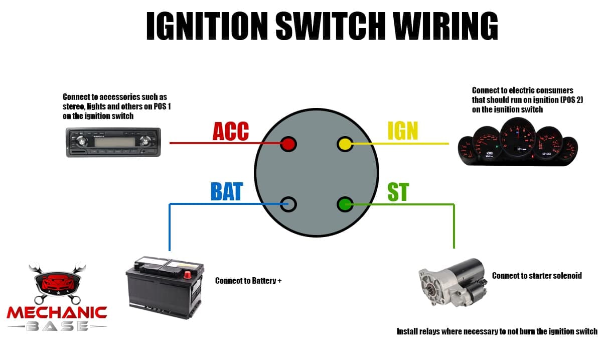
- Ignition Switch: The heart of the system. This is the physical switch you turn with your key. It has multiple positions: LOCK, ACC (Accessory), ON (Run), and START.
- Battery (B+ or BAT): The source of power for the entire system. Usually shown as a stylized battery symbol.
- Starter Solenoid/Relay: A heavy-duty switch that engages the starter motor. It receives a signal from the ignition switch (START position) to activate.
- Starter Motor: The electric motor that cranks the engine.
- Fuses and Circuit Breakers: Protective devices that prevent damage from overcurrent. They are shown with various symbols.
- Relays: Electrically operated switches that control circuits with high current draw, using a low-current signal from the ignition switch.
- Resistors: Components that limit current flow. May be used to reduce voltage to certain circuits.
- Ground (GND): The return path for the electrical current, typically connected to the vehicle's chassis.
You'll also encounter various wiring specifications on the diagram, such as:
- Wire Gauge (AWG): Specifies the wire thickness, impacting its current-carrying capacity. Crucial for safety!
- Wire Color Codes: Each wire is assigned a color (e.g., Red, Blue/White, Black) for identification. This is *critical* for tracing circuits.
- Circuit Numbers: Some diagrams label each circuit with a unique number, further aiding identification and troubleshooting.
Deciphering the Symbols: Lines, Colors, and Icons
Understanding the symbols is fundamental to reading any wiring diagram. Here's a breakdown:
- Lines: Represent wires. Solid lines typically indicate positive circuits, while dashed lines might represent ground or control signals. The thickness of the line *sometimes* correlates to the wire gauge, although this isn't always consistent across diagrams.
- Colors: As mentioned earlier, wire colors are crucial. Standard color codes exist, but they can vary slightly between manufacturers. The diagram will usually include a legend defining each color (e.g., "Red = +12V," "Black = Ground").
- Icons: Standardized symbols represent components. Here are a few common ones:
- Battery: A stylized representation of a battery, often with "+" and "-" markings.
- Fuse: A zigzag line inside a rectangle or circle.
- Relay: A square or rectangle with a coil symbol inside, and lines indicating the switch contacts.
- Ground: Three horizontal lines, decreasing in size.
- Resistor: A zigzag line.
- Diode: A triangle with a line at its point.
- Ignition Switch: A series of circles connected by lines, representing the different switch positions (LOCK, ACC, ON, START).
Also, pay attention to junction points – where wires connect. These are usually shown as dots. If a line crosses another without a dot, it means the wires *do not* connect at that point.
How It Works: The Ignition Sequence
The ignition switch wiring diagram illustrates the sequence of events that occur when you turn the key. Here's a simplified overview:
- LOCK Position: The key is removed. No circuits are active (except possibly the clock or alarm system, which are usually powered directly from the battery).
- ACC (Accessory) Position: Power is supplied to accessory circuits like the radio, cigarette lighter, and potentially other convenience features. The engine is *not* running.
- ON (Run) Position: Power is supplied to the engine management system (ECU/PCM), fuel pump, ignition system (spark plugs), and all other essential circuits for normal operation. The engine is *not* cranking yet.
- START Position: This position momentarily sends power to the starter solenoid/relay. The solenoid engages the starter motor, which cranks the engine. Once the engine starts, you release the key, and it springs back to the ON position.
The wiring diagram will show you exactly which circuits are energized in each of these positions. For example, you'll see which wire carries power from the battery to the ignition switch, and which wires carry power from the ignition switch to the various circuits in each position.
Real-World Use: Basic Troubleshooting Tips
Armed with the diagram, you can start troubleshooting ignition problems. Here are a few basic tips:
- No Power at All: Check the battery voltage and the main fuse supplying power to the ignition switch. Use a multimeter to verify voltage at the ignition switch's input terminal (typically labeled B+ or BAT).
- No Start, But Accessories Work: The issue is likely in the START circuit. Check the wire running from the ignition switch (START position) to the starter solenoid. Look for a blown fuse, a corroded connection, or a faulty starter solenoid.
- Accessories Don't Work in ACC Position: Check the fuse for the accessory circuit. Also, verify that the ignition switch is actually making contact in the ACC position (use a multimeter to check for voltage at the accessory wire coming from the switch).
- Intermittent Problems: These are the trickiest. Look for loose connections, corroded terminals, or damaged wiring. Gently wiggle wires while monitoring voltage to see if you can identify the source of the intermittent connection.
Important Tool: A multimeter is your best friend when troubleshooting electrical problems. Learn how to use it to check for voltage, continuity, and resistance. A test light can also be useful for quickly checking for power in a circuit.
Safety: Highlight Risky Components
Working with electrical systems can be dangerous. Here are some safety precautions:
- Disconnect the Battery: Always disconnect the negative battery terminal before working on the electrical system. This prevents accidental short circuits and potential electrocution.
- Handle Wires Carefully: Avoid touching bare wires, especially when the battery is connected.
- Use Proper Tools: Use insulated tools designed for electrical work.
- Don't Modify Fuses: Never replace a fuse with a higher amperage rating. This can overload the circuit and cause a fire.
- High-Current Components: The starter motor and starter solenoid handle very high currents. Be extremely cautious when working on these components. Accidental short circuits can cause sparks, heat, and even burns.
Warning! The ignition system contains potentially high-voltage components, especially in older vehicles with points-type ignition systems. Be extremely careful when working around these components, and always follow the manufacturer's safety guidelines.
Now that you have a solid understanding of hotwire ignition switch wiring diagrams, you're well-equipped to diagnose and repair electrical problems in your vehicle's starting system. Remember to always prioritize safety and double-check your work.
And that ignition switch wiring diagram we promised? It's ready for you. You can download it using the link below. This file contains a generic example of an ignition switch wiring diagram, but remember to consult the specific diagram for your vehicle's make and model for the most accurate information. Happy wrenching!
We have the file, and reader can download the diagram. (Download Link Placeholder)