How Does A Clutch Work Diagram
Alright, let's dive into the inner workings of a clutch system using a detailed diagram. Understanding how a clutch works, and being able to interpret a diagram depicting its function, is crucial for intermediate car owners, DIY mechanics, and anyone looking to perform their own repairs, upgrades, or even just diagnose issues accurately. This isn't just about spinning wrenches; it's about understanding the foundational principles of how your vehicle transmits power.
Purpose of the Clutch Diagram
Why bother with a clutch diagram? Simple. It’s your visual roadmap to understanding a complex system. The diagram serves several vital purposes:
- Troubleshooting: When you're experiencing clutch slippage, chatter, or difficulty shifting, the diagram helps you pinpoint potential problem areas.
- Repair and Replacement: Before tearing into your transmission, the diagram illustrates the order of components, helping you avoid costly mistakes.
- Performance Upgrades: Considering a performance clutch? Understanding the stock setup allows you to appreciate the benefits and potential drawbacks of different upgrades.
- Learning and Education: For the DIY enthusiast, the diagram demystifies the clutch system, providing a deeper understanding of vehicle mechanics.
We even have a downloadable diagram available to you. This diagram will let you zoom in and more easily grasp all the parts we discuss.
Key Specs and Main Parts
Before we dissect the diagram, let's identify the key components of a typical clutch system. The specs might vary depending on the make and model of your vehicle, but the underlying principles remain the same:
- Flywheel: A heavy, rotating disc bolted to the engine's crankshaft. Its primary functions are to store rotational energy and provide a friction surface for the clutch disc. Key spec here is diameter and weight.
- Clutch Disc (or Clutch Plate): A circular plate with a friction material lining on both sides. This is the component that physically engages with the flywheel to transmit engine power to the transmission. Important specs are diameter, friction material type, and number of springs.
- Pressure Plate: A spring-loaded mechanism that clamps the clutch disc against the flywheel. This is controlled by the clutch pedal. Key specs are clamping force (measured in lbs/ft) and overall design (diaphragm spring or coil spring).
- Release Bearing (or Throw-Out Bearing): A bearing that pushes against the pressure plate's release fingers, disengaging the clutch.
- Clutch Fork (or Release Lever): A lever that pivots to move the release bearing. It's usually actuated by a cable or hydraulic system.
- Clutch Master Cylinder (Hydraulic Systems): A cylinder connected to the clutch pedal that creates hydraulic pressure to actuate the slave cylinder.
- Clutch Slave Cylinder (Hydraulic Systems): A cylinder that receives hydraulic pressure from the master cylinder and moves the clutch fork.
- Clutch Cable (Cable-Operated Systems): A cable connecting the clutch pedal directly to the clutch fork.
Decoding the Diagram: Symbols and Conventions
Clutch diagrams, like all technical diagrams, use specific symbols and conventions to represent components and their interactions. Understanding these symbols is critical to interpreting the diagram correctly.
- Solid Lines: Typically represent mechanical connections, such as the linkage between the clutch fork and the release bearing, or the bolts connecting the flywheel to the crankshaft.
- Dashed Lines: Often indicate hydraulic lines or control cables. They can also show connections that exist but are not immediately visible in the diagram's primary view.
- Arrows: Indicate the direction of force or movement. For instance, an arrow might show the direction in which the clutch fork moves the release bearing.
- Cross-hatching: Represents friction surfaces. You'll typically see this on the clutch disc and the flywheel.
- Color Coding: Some diagrams use color to differentiate components or systems (e.g., blue for hydraulic lines, red for mechanical parts). However, color usage can vary, so always refer to the diagram's legend.
- Standardized Icons: You might encounter standardized icons for specific components, such as cylinders (master and slave cylinders) or springs.
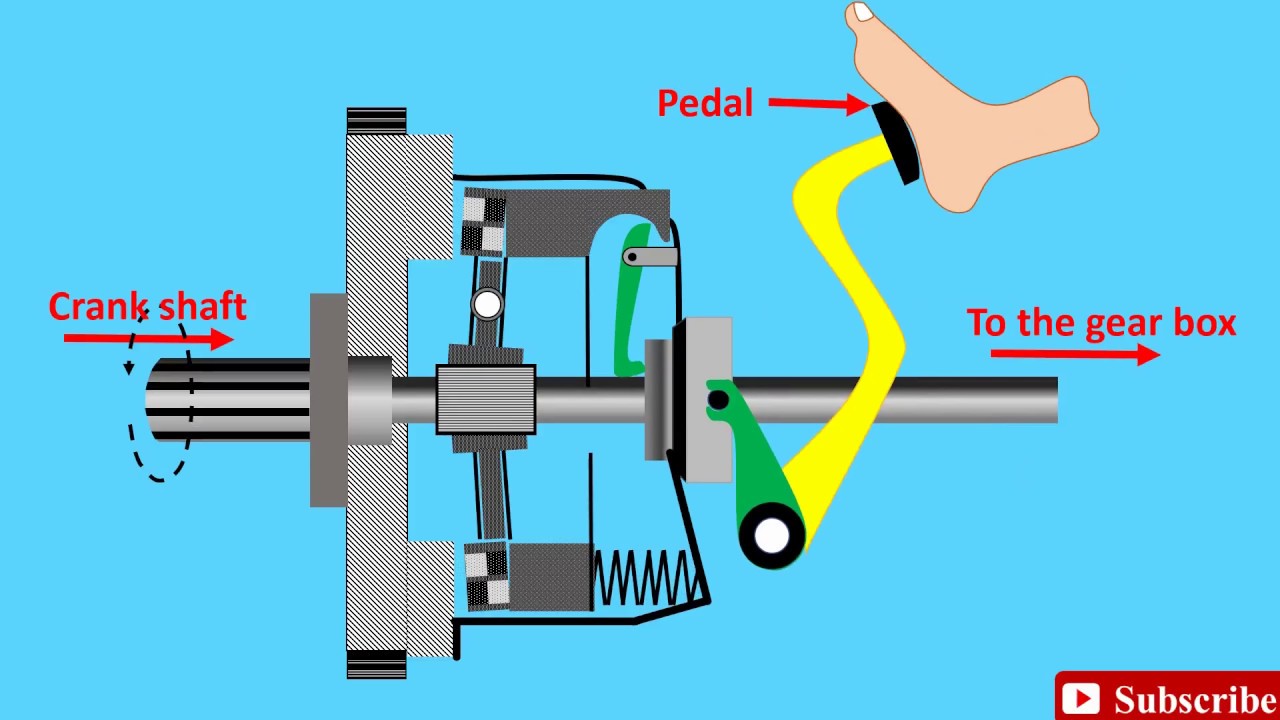
How It Works: The Clutch in Action
Now let's break down the operational process. When the clutch pedal is not depressed (clutch engaged):
- The pressure plate, driven by the engine through the flywheel, firmly clamps the clutch disc against the flywheel's friction surface.
- This creates a direct connection between the engine and the transmission input shaft.
- Engine power is transferred through the flywheel, clutch disc, and into the transmission, allowing the vehicle to move.
When the clutch pedal is depressed (clutch disengaged):
- The clutch pedal actuates either a cable or a hydraulic system (master and slave cylinders).
- This movement forces the clutch fork to push the release bearing against the pressure plate's release fingers.
- The pressure plate retracts, releasing its clamping force on the clutch disc.
- The connection between the engine and the transmission is broken. The transmission can now be shifted into another gear, or the vehicle can be brought to a stop without stalling the engine.
The process of releasing the clutch pedal allows the pressure plate to re-engage, re-establishing the connection and smoothly transferring power back to the transmission. The smoother this transition, the less strain on the system and the smoother the driving experience.
Real-World Use: Basic Troubleshooting
Equipped with the diagram and an understanding of the clutch system, you can tackle some basic troubleshooting:
- Clutch Slippage: Engine revs high, but the car doesn't accelerate proportionally. Potential causes include a worn clutch disc, oil contamination on the friction surfaces, or a weak pressure plate. The diagram helps you visualize where these components are located for inspection.
- Clutch Chatter: Jerky engagement of the clutch. Possible causes include a warped flywheel or clutch disc, worn engine mounts, or a faulty pressure plate. The diagram helps you verify the flatness and alignment of these components.
- Difficulty Shifting: Hard to get into gear, especially first or reverse. This could indicate a problem with the clutch not fully disengaging. Check for a worn release bearing, a stretched clutch cable, or a malfunctioning hydraulic system (leaks, air in the lines). The diagram highlights the linkages and fluid lines that need inspection.
- Clutch Pedal Feels Spongy: Usually indicates an air bubble in the hydraulic system, or a leaking master or slave cylinder. Again, the diagram points you to these vital parts of the hydraulic system.
Note: Always start with the simplest checks first (cable adjustment, fluid levels) before assuming a major component failure.
Safety Considerations
Working on a clutch system involves some inherent risks:
- High Tension Springs: The pressure plate contains powerful springs that can cause serious injury if released improperly. Use a clutch alignment tool during removal and installation to control the spring force.
- Flywheel Weight: The flywheel is heavy and can cause injury if dropped. Always use proper lifting techniques and support the flywheel adequately.
- Hydraulic Fluid: Clutch fluid can irritate skin and eyes. Wear gloves and eye protection when working with hydraulic systems.
- Vehicle Support: Always use jack stands to securely support the vehicle before working underneath it. Never rely solely on a jack.
- Brake Cleaner and Solvents: Be careful when using brake cleaner or solvents, as they can damage certain clutch components.
Remember, if you're uncomfortable with any aspect of the repair, consult a qualified mechanic. It's better to be safe than sorry.
By using the clutch diagram and understanding the steps we just outlined, you will be in a much better position to do your own work on your clutch!