
How Does A Hydrogen Engine Work Diagram
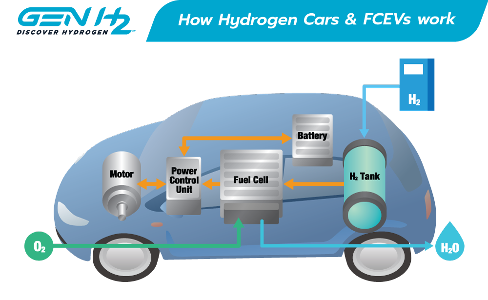
So, you're looking to understand how a hydrogen engine works, eh? Excellent! Grasping the intricacies of these powerplants can be incredibly useful, whether you're diagnosing a performance issue, contemplating a conversion project, or simply expanding your automotive knowledge. This is where a detailed hydrogen engine diagram becomes your best friend. We're going to break down everything, from the basic components to potential issues, making it clear and easy to understand.
Purpose of a Hydrogen Engine Diagram
Think of a hydrogen engine diagram as a roadmap for your engine. It serves several crucial purposes:
- Troubleshooting and Repair: The diagram helps you pinpoint the location of components and trace connections, essential for diagnosing faults and making repairs. Knowing where everything is *supposed* to be is half the battle.
- Understanding Engine Operation: It provides a visual representation of the engine's systems, allowing you to understand how the hydrogen fuel system interacts with the air intake, combustion chamber, and exhaust system.
- Modification and Conversion: If you're considering modifying an existing engine or converting it to run on hydrogen, the diagram is vital for planning and executing the project safely and effectively.
- Educational Resource: For anyone looking to learn more about alternative fuel vehicles and engine technology, the diagram offers a clear and concise overview of the hydrogen engine's operation.
Key Specs and Main Parts
Let's dive into the main components you'll find on a typical hydrogen engine diagram. Remember that engine designs can vary, but these are the essentials:
- Hydrogen Fuel Tank: This is where the compressed hydrogen gas (H2) is stored. It's a high-pressure vessel designed for safety and durability. Key specs include its volume (e.g., 7 kg H2), maximum working pressure (e.g., 700 bar), and safety features like pressure relief devices.
- Fuel Injectors: These precision devices spray hydrogen into the intake manifold or directly into the combustion chamber. Specs to note include the injection rate (grams per second) and operating pressure.
- Engine Control Unit (ECU): The brain of the operation. The ECU controls the fuel injection timing, spark timing (if applicable), and other engine parameters to optimize performance and efficiency.
- Air Intake System: Just like a gasoline engine, a hydrogen engine needs air for combustion. The air intake system includes the air filter, throttle body, and intake manifold.
- Combustion Chamber: This is where the magic happens! The hydrogen and air mix and ignite, creating the power that drives the pistons.
- Exhaust System: The exhaust system carries the combustion byproducts away from the engine. In a hydrogen engine, the primary byproduct is water vapor (H2O), making it much cleaner than gasoline engines.
- Sensors: Numerous sensors monitor engine parameters, including manifold air pressure (MAP), throttle position (TPS), coolant temperature (ECT), and exhaust oxygen (O2). These sensors provide feedback to the ECU, allowing it to make adjustments to optimize engine performance.
- Fuel Pressure Regulator: This device maintains a constant fuel pressure at the fuel injectors, ensuring consistent fuel delivery.
- Hydrogen Leak Detection System: Crucial for safety, this system monitors for hydrogen leaks and can shut down the engine in the event of a leak.
Symbols and Conventions in the Diagram
Understanding the symbols and conventions used in a hydrogen engine diagram is essential for accurate interpretation. Here's a breakdown of some common elements:
- Lines: Different types of lines represent different types of connections. Solid lines typically indicate fuel lines, air lines, or mechanical linkages. Dashed lines often represent electrical connections or vacuum lines. Dotted lines may indicate diagnostic signals or less critical connections.
- Colors: Color coding can be used to differentiate between different systems. For example, fuel lines might be colored blue, air lines green, and electrical wires red or black. However, color coding can vary between diagrams, so always refer to the diagram's legend.
- Icons: Icons represent specific components. A fuel pump might be represented by a stylized pump symbol, a sensor by a rectangle with a wavy line, and an ECU by a chip icon. These icons are usually standardized, but always check the legend for clarification.
- Flow Arrows: Arrows indicate the direction of flow for fluids (hydrogen, air, coolant) and electrical signals.
- Abbreviations: Diagrams often use abbreviations to save space. Refer to the diagram's legend for a list of abbreviations and their meanings. Some examples include:
- H2: Hydrogen gas
- ECU: Engine Control Unit
- MAP: Manifold Absolute Pressure
- TPS: Throttle Position Sensor
- ECT: Engine Coolant Temperature
How It Works: The Hydrogen Engine Cycle
Let's walk through the basic operation of a hydrogen engine. In most hydrogen engines, the combustion process mirrors that of a traditional gasoline engine, following the four-stroke cycle (intake, compression, power, exhaust):
- Intake Stroke: The intake valve opens, and the piston moves down, drawing a mixture of air and hydrogen into the cylinder. In some designs, only air is drawn in, and hydrogen is injected directly into the cylinder.
- Compression Stroke: The intake valve closes, and the piston moves up, compressing the air-hydrogen mixture. This increases the temperature and pressure, preparing it for combustion.
- Power Stroke: A spark plug ignites the compressed mixture. The rapid expansion of the burning gases forces the piston down, generating power.
- Exhaust Stroke: The exhaust valve opens, and the piston moves up, pushing the exhaust gases (primarily water vapor) out of the cylinder.
Some hydrogen engines use direct injection, where hydrogen is injected directly into the cylinder instead of the intake manifold. This allows for more precise control over the combustion process and can improve efficiency. Stoichiometry (the ideal air-fuel ratio) is different for hydrogen than gasoline, requiring precise control by the ECU.
Real-World Use: Basic Troubleshooting
Let's say your hydrogen engine is experiencing performance issues. Here are some basic troubleshooting steps using the diagram:
- Rough Idling or Stalling: Check the fuel injectors for proper operation. Use the diagram to locate the injectors and verify their connections. Look for potential leaks around the fuel lines and fittings.
- Poor Fuel Economy: Check the oxygen sensor (O2 sensor) for proper operation. A faulty O2 sensor can cause the ECU to inject too much or too little hydrogen, leading to poor fuel economy.
- Engine Misfires: If your engine is misfiring, check the spark plugs (if applicable) and ignition system. Also, verify that the fuel injectors are delivering the correct amount of hydrogen to each cylinder.
- Hydrogen Leak: Immediately shut down the engine and ventilate the area. Use a hydrogen leak detector to pinpoint the source of the leak. Refer to the diagram to identify potential leak points, such as fuel lines, fittings, and the fuel tank.
Remember to always consult your vehicle's service manual for specific troubleshooting procedures. The diagram provides a general overview, but the service manual will offer detailed instructions and diagnostic codes.
Safety Considerations
Working with hydrogen engines requires strict adherence to safety protocols. Hydrogen is a highly flammable gas, and leaks can pose a significant fire hazard. Here are some key safety considerations:
- Hydrogen Fuel Tank: The hydrogen fuel tank is a high-pressure vessel and should be handled with extreme care. Never attempt to modify or repair the tank yourself. Always consult a qualified technician.
- Fuel Lines and Fittings: Ensure that all fuel lines and fittings are properly tightened and in good condition. Leaks can occur if connections are loose or corroded.
- Ventilation: Work in a well-ventilated area when working on the fuel system. This will help prevent the accumulation of hydrogen gas in the event of a leak.
- Spark Hazards: Avoid creating sparks or open flames near the fuel system. Hydrogen can ignite easily, so take precautions to prevent any potential ignition sources.
- Hydrogen Leak Detector: Use a hydrogen leak detector to check for leaks before starting the engine after working on the fuel system.
Crucially, never smoke or use open flames near the hydrogen fuel system. A single spark can ignite a hydrogen leak, leading to a dangerous explosion.
We have the hydrogen engine diagram file prepared for you. You can download the file for closer inspection.