
How Does Air Conditioner Work Diagram
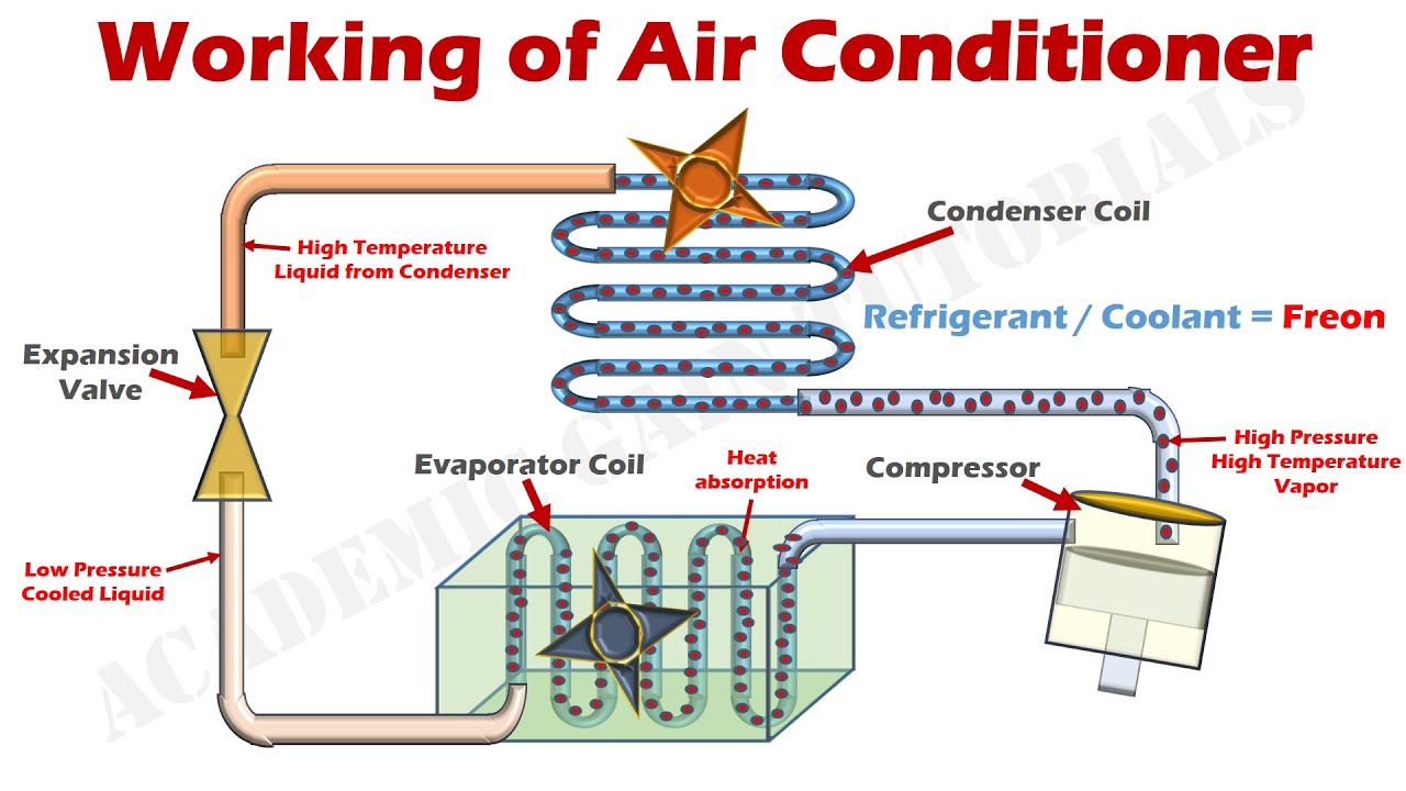
Okay, let's dive into the heart of your car's climate control – the air conditioning system. This isn't just about blowing cold air; it's a complex thermodynamic process, and understanding how it works is crucial for troubleshooting, performing basic maintenance, or even just appreciating the engineering that keeps you comfortable on those sweltering summer days. We're going to break down the AC system using the air conditioner work diagram as our roadmap.
Purpose of the AC System Diagram
Why bother with a diagram? Think of it as the schematics for your AC system. It's invaluable for several reasons:
- Troubleshooting: When your AC isn't blowing cold, the diagram helps you trace the refrigerant flow and identify potential problem areas like leaks, blockages, or faulty components.
- Repairing: If you're replacing a compressor, condenser, or any other part, the diagram shows you how everything connects and where to find specific components.
- Learning: Even if you're not planning on DIY repairs, understanding the system's operation allows you to diagnose issues earlier and communicate more effectively with your mechanic.
- Modifications: Planning to upgrade or modify your AC system? The diagram provides a foundation for understanding the existing setup.
We have a downloadable version of a typical automotive AC system diagram available for you, linked at the end of this article. It’ll be a useful reference as we proceed.
Key Specs and Main Parts
Every AC system, regardless of vehicle, operates on the same fundamental principles. Let's cover the main players and their roles:
Main Components:
- Compressor: The heart of the system. It's a pump that pressurizes the refrigerant, raising its temperature. Think of it as the engine that drives the entire cooling cycle.
- Condenser: Located at the front of the car (usually near the radiator), the condenser releases heat from the high-pressure, high-temperature refrigerant, causing it to condense from a gas into a liquid.
- Receiver-Drier (or Accumulator): This component filters the refrigerant and removes moisture. Moisture is a major enemy of the AC system, as it can react with the refrigerant and create corrosive acids. Receiver-driers are typically used with expansion valves, while accumulators are used with orifice tubes (more on those later).
- Expansion Valve (or Orifice Tube): This is the metering device that controls the flow of refrigerant into the evaporator. It causes a pressure drop, which in turn lowers the refrigerant's temperature. An expansion valve is a sophisticated component that dynamically adjusts the refrigerant flow based on the system's temperature and pressure. An orifice tube is a simpler, fixed-size restriction.
- Evaporator: Located inside the passenger compartment, the evaporator absorbs heat from the cabin air, causing the refrigerant to boil and turn back into a gas. This is where the cooling actually happens. A blower motor forces air across the evaporator fins, circulating the cooled air throughout the car.
- Refrigerant: The working fluid that circulates throughout the system, absorbing and releasing heat. Modern cars typically use R-134a, but newer systems are transitioning to R-1234yf (which is mildly flammable). Older vehicles may use R-12 (which is no longer in production). Never mix refrigerants!
Key Specs to Consider:
- Refrigerant Type and Capacity: Specified by the manufacturer. Using the wrong refrigerant or the wrong amount can damage the system. Refer to the sticker under your hood or your owner's manual.
- Compressor Type: There are different types of compressors (e.g., scroll, piston, rotary), each with its own characteristics.
- Operating Pressures: Knowing the normal high-side and low-side pressures is crucial for diagnosing problems. These pressures vary depending on ambient temperature and engine speed.
Symbols – Understanding the Diagram's Language
The AC system diagram uses specific symbols to represent components and connections. Here's a breakdown of the common ones:
Lines:
- Solid Lines: Typically represent refrigerant lines. Their thickness might indicate the diameter of the line.
- Dashed Lines: Often indicate electrical wiring or control signals.
- Dotted Lines: May represent vacuum lines or reference lines in the diagram.
Colors:
- Color Coding: Colors can represent different refrigerant pressures or temperatures. For example, red might indicate high-pressure, high-temperature refrigerant, while blue might indicate low-pressure, low-temperature refrigerant. Consult the legend on the diagram.
Icons:
- Compressor: Usually depicted as a stylized pump or a circle with a 'C' inside.
- Condenser: Often shown as a radiator-like grid.
- Receiver-Drier/Accumulator: Typically represented as a cylinder with desiccant material indicated.
- Expansion Valve/Orifice Tube: May be depicted as a valve symbol or a simple restriction.
- Evaporator: Similar to the condenser, but located inside the passenger compartment.
- Pressure Switches: Shown as switches that respond to pressure changes. These are safety devices that protect the system from over-pressure or low-pressure conditions.
How It Works: The Refrigeration Cycle
The AC system works by cycling refrigerant through a series of phase changes (liquid to gas and back again), absorbing and releasing heat along the way. Here's a step-by-step explanation:
- Compression: The compressor takes in low-pressure, low-temperature refrigerant gas and compresses it. This increases its pressure and temperature, turning it into a high-pressure, high-temperature gas.
- Condensation: The hot, high-pressure gas flows to the condenser, where it releases heat to the outside air. As it cools, the refrigerant condenses into a high-pressure, high-temperature liquid.
- Filtration and Drying: The high-pressure liquid refrigerant flows to the receiver-drier (or accumulator), where it's filtered and dried to remove any contaminants or moisture.
- Expansion: The high-pressure liquid refrigerant flows through the expansion valve (or orifice tube). This creates a restriction, causing a pressure drop and a significant temperature decrease. The refrigerant becomes a low-pressure, low-temperature liquid.
- Evaporation: The cold, low-pressure liquid refrigerant enters the evaporator, where it absorbs heat from the air blowing across it. This causes the refrigerant to boil and turn back into a low-pressure, low-temperature gas, cooling the air in the process.
- Back to the Compressor: The low-pressure gas returns to the compressor, and the cycle begins again.
Real-World Use: Basic Troubleshooting Tips
Using the diagram, you can pinpoint potential problems. Here are some basic troubleshooting steps:
- No Cold Air: Check the compressor clutch. Is it engaging? If not, check the electrical connections, the pressure switches, and the compressor itself. The diagram will show you the location of these components.
- Weak Airflow: Inspect the blower motor and the evaporator core. Is the blower motor running at full speed? Is the evaporator core clogged with debris?
- Leaks: Look for signs of refrigerant leaks, such as oily residue, at the connections between components. A UV dye can help locate leaks.
- Pressure Readings: Use gauges to check the high-side and low-side pressures. Compare these readings to the manufacturer's specifications. Abnormal pressures can indicate a problem with the compressor, expansion valve, or refrigerant charge.
Safety First! Highlighting Risky Components
Working on AC systems can be dangerous if you're not careful. Here are some safety precautions:
- Refrigerant: Refrigerant can cause frostbite and is harmful if inhaled. Wear gloves and eye protection when handling refrigerant.
- High Pressure: The high-side of the system operates at very high pressures. Never disconnect any lines while the system is pressurized.
- Electrical: Disconnect the battery before working on any electrical components of the AC system.
- Proper Tools: Use the correct tools for the job. Don't try to improvise.
- Recovery and Disposal: Never vent refrigerant into the atmosphere. It's illegal and harmful to the environment. Use a refrigerant recovery machine to recover and recycle the refrigerant.
- Flammable Refrigerant: If your vehicle uses R-1234yf refrigerant, be extra cautious. This refrigerant is mildly flammable. Avoid open flames or sparks near the system.
Remember, if you're not comfortable working on the AC system yourself, take your car to a qualified mechanic.
You can download the typical automotive AC system diagram here. This will provide you with a visual aid to better understand the components and their layout within the AC system. Happy wrenching!