
How Does Air Conditioning Work Diagram
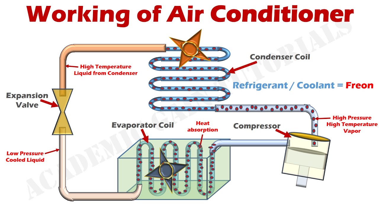
Alright, let's dive into the heart of your car's climate control system: the air conditioning. Understanding how your AC works isn't just about impressing your buddies at the next car meet; it's a practical skill that can save you money on repairs and help you diagnose problems before they turn into major headaches. This article will break down the AC system using a typical system diagram, explaining the components, how they interact, and how to interpret those confusing lines and symbols. We're aiming for a 'trusted mechanic explaining it clearly to an experienced DIYer' vibe, so expect technical terms explained, but don't expect hand-holding.
Why This Diagram Matters
Having access to and understanding an AC system diagram is incredibly valuable for several reasons:
- Troubleshooting: When your AC stops blowing cold, the diagram acts as a roadmap for tracing the problem. You can systematically check components and connections to isolate the faulty part.
- Repair and Replacement: Whether you're replacing a leaking hose or swapping out the compressor, the diagram shows you exactly where things are located and how they connect, minimizing errors.
- Performance Tuning: Understanding the flow and function allows you to identify potential bottlenecks or inefficiencies in the system, potentially leading to upgrades that improve cooling performance. Think bigger condensers, better expansion valves – stuff that'll make you the envy of everyone at the track.
- Learning and Education: Even if you don't plan on doing your own repairs, understanding the basic principles of your car's AC is just plain cool (pun intended!). It empowers you to make informed decisions when dealing with mechanics.
Essentially, the diagram transforms the black box of your AC system into a transparent and understandable process.
Key Specs and Main Parts
Before we dissect the diagram itself, let's review the core components of a typical automotive AC system:
- Compressor: The heart of the system. The compressor pumps refrigerant throughout the system, increasing its pressure and temperature. Driven by the engine via a belt.
- Condenser: Located at the front of the car, often near the radiator. The condenser cools and condenses the high-pressure refrigerant from a gas into a liquid.
- Receiver/Drier (or Accumulator): A filter and reservoir that removes moisture and contaminants from the refrigerant. The receiver/drier also stores excess refrigerant. Accumulators are usually found on systems using an orifice tube, while receiver/driers are on systems using thermal expansion valves.
- Expansion Valve (or Orifice Tube): This metering device controls the flow of refrigerant into the evaporator. The expansion valve reduces the pressure of the refrigerant, causing it to expand and cool dramatically.
- Evaporator: Located inside the passenger compartment, usually behind the dashboard. The evaporator absorbs heat from the air passing through it, cooling the air that blows into the cabin.
- Refrigerant Lines: These hoses and pipes connect all the components, carrying the refrigerant throughout the system. High-pressure lines carry the hot, compressed refrigerant, while low-pressure lines carry the cool, expanded refrigerant.
- Pressure Switches: These safety devices monitor the pressure in the system and can shut off the compressor if the pressure is too high or too low.
Decoding the Diagram: Symbols and Conventions
AC system diagrams use standardized symbols to represent components and lines. Here's a guide to understanding the most common symbols:
- Solid Lines: Typically represent refrigerant lines. The thickness of the line might indicate the size of the line or simply be for visual clarity.
- Dashed Lines: Usually represent electrical wiring or control signals.
- Arrows: Indicate the direction of refrigerant flow.
- Boxes or Rectangles: Represent components like the compressor, condenser, evaporator, and receiver/drier. Some diagrams use stylized icons for these components.
- Circles or Spheres: Often represent pressure switches or sensors.
- Diamond shape: Often used to represent the orifice tube
- Color Coding: While not always consistent, some diagrams use color to differentiate between high-pressure and low-pressure lines. Red might indicate high-pressure, and blue might indicate low-pressure, but *always* check the diagram's key.
Important! Different manufacturers might use slightly different symbols, so always refer to the legend or key that accompanies the diagram. Also, note that the diagrams are often simplified representations and don't show the exact physical layout of the components in your car. They're more concerned with the functional relationships between the parts.
How It Works: The Refrigeration Cycle
Now, let's trace the refrigerant's journey through the system. The refrigeration cycle is the core principle behind how AC works:
- Compression: The compressor receives low-pressure, low-temperature refrigerant gas and compresses it, increasing its pressure and temperature. Think of it like squeezing a can of compressed air – it gets hot.
- Condensation: The hot, high-pressure refrigerant gas flows to the condenser. As air flows across the condenser, the refrigerant cools and condenses into a high-pressure liquid. Heat is dissipated into the surrounding air.
- Metering/Expansion: The high-pressure liquid refrigerant then flows to the expansion valve or orifice tube. This is where the magic happens. The expansion valve restricts the flow of refrigerant, causing a dramatic pressure drop. This pressure drop allows the refrigerant to expand and vaporize, resulting in a significant temperature drop.
- Evaporation: The cold, low-pressure refrigerant flows into the evaporator. As air from the cabin is blown across the evaporator, the refrigerant absorbs heat, causing it to vaporize back into a gas. This process cools the air, which is then blown into the passenger compartment.
- Cycle Repeats: The low-pressure, low-temperature refrigerant gas then returns to the compressor, and the cycle begins again.
The receiver/drier or accumulator plays a crucial role by storing excess refrigerant and removing moisture, ensuring the system operates efficiently and preventing damage.
Real-World Use: Basic Troubleshooting
So, your AC isn't blowing cold. Where do you start? Here are a few basic troubleshooting tips using the diagram as your guide:
- No Cold Air at All: Check the compressor clutch. Is it engaging when the AC is turned on? If not, check the electrical connections, pressure switches, and the compressor itself. Refer to the diagram to trace the wiring and identify the relevant components.
- Weak Cooling: Check the refrigerant level. Low refrigerant can significantly reduce cooling performance. If you're equipped and trained to do so, you can use gauges to check the pressures on the high and low sides of the system. The diagram will show you where the service ports are located.
- Strange Noises: Grinding or rattling noises from the compressor could indicate a failing compressor. The diagram can help you identify the compressor and its connections for removal and replacement.
- Leaks: Look for oily residue around fittings and connections. This is often a sign of a refrigerant leak. The diagram will help you pinpoint the location of the leak and identify the affected component.
Remember: Diagnosing AC problems often requires specialized tools and knowledge. If you're not comfortable working with refrigerant or electrical systems, it's best to consult a qualified mechanic.
Safety First!
Working with AC systems can be dangerous if you're not careful. Refrigerant can cause frostbite if it comes into contact with your skin or eyes, and high-pressure lines can burst if damaged.
- Refrigerant: Never release refrigerant into the atmosphere. It's harmful to the environment and illegal in many places. Always recover refrigerant using proper equipment.
- High Pressure: Be extremely cautious when working with high-pressure lines. Never disconnect a line while the system is pressurized.
- Electrical: Disconnect the battery before working on any electrical components of the AC system.
- Tools: Use the correct tools for the job. Don't try to force anything or cut corners.
- Training: If you're not familiar with AC systems, take a course or consult with a qualified mechanic before attempting any repairs.
The most important thing is to prioritize safety. Err on the side of caution and don't attempt anything you're not comfortable with.
You now have a solid understanding of how your car's AC system works and how to interpret a typical system diagram. Remember, this knowledge is power. Use it wisely and stay cool!
As mentioned, we have an example AC system diagram file ready for you. It's a great visual aid to have on hand while you're working. You can download it here: [Download Link - Placeholder, obviously!]. Good luck with your repairs!