
How Does An Air Conditioner Work Diagram
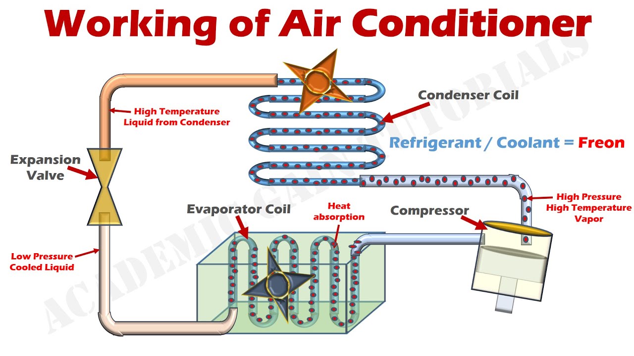
Let's dive into understanding how your car's air conditioner works. This knowledge isn't just for curiosity; it's a crucial skill for diagnosing problems, performing basic repairs, and even deciding when it's best to hand things over to a professional. Having a good grasp of the AC system and the ability to read an AC system diagram can save you money and keep you comfortable on those hot days.
Why Bother with an AC Diagram?
Understanding the system through a diagram allows for targeted diagnostics. Instead of blindly replacing parts, you can trace the flow of refrigerant, identify potential bottlenecks, and pinpoint faulty components. Plus, if you're into modifying your vehicle, especially engine swaps or custom builds, knowing how the AC system integrates will be invaluable. Furthermore, with the diagram, you can easily and quickly locate and identify the key components.
Key Specs and Main Parts
Before we dissect the diagram, let's review the main components. The automotive AC system is a closed-loop system, meaning the refrigerant continually cycles through it. The five major components are:
- Compressor: The heart of the system. It's a pump that compresses the refrigerant gas, raising its pressure and temperature.
- Condenser: Located in front of the radiator, the condenser dissipates heat from the high-pressure, high-temperature refrigerant gas, turning it into a high-pressure liquid.
- Receiver/Drier (or Accumulator): This component filters debris and removes moisture from the refrigerant. It also acts as a reservoir. Newer systems typically use an accumulator.
- Expansion Valve (or Orifice Tube): This metering device regulates the flow of refrigerant into the evaporator. It causes a pressure drop, allowing the refrigerant to expand and cool dramatically.
- Evaporator: Located inside the vehicle's dashboard, the evaporator absorbs heat from the cabin air as the low-pressure, low-temperature refrigerant boils and turns back into a gas.
Refrigerant itself is a critical component. Older vehicles used R-12, but most modern vehicles use R-134a or the newer R-1234yf. These refrigerants have different pressures and characteristics, so it's vital to use the correct type.
Decoding the AC Diagram: Lines, Colors, and Icons
An AC system diagram is a schematic representation of the refrigerant flow. Here's how to interpret the common symbols:
- Lines: Solid lines represent refrigerant lines (hoses or metal tubes). Dashed lines might represent electrical wiring or control signals.
- Colors: While not universally standardized, some diagrams use color coding. Typically:
- Red indicates high-pressure refrigerant.
- Blue indicates low-pressure refrigerant.
- Green might indicate a ground connection.
- Other colors may be used for electrical wiring, with a legend explaining their meaning.
- Icons: Each component has a simplified symbol:
- Compressor: Often a circle with an arrow indicating rotation.
- Condenser: Represented by a series of zig-zag lines, suggesting heat dissipation.
- Receiver/Drier or Accumulator: A cylindrical shape, sometimes with a desiccant symbol.
- Expansion Valve: A triangular symbol with an arrow indicating the flow direction. Orifice tubes might be a simple restriction in the line.
- Evaporator: Similar to the condenser, but often enclosed in a box representing the evaporator housing.
- Pressure Switches: Small squares or circles with electrical connections.
The diagram will also show the direction of refrigerant flow with arrows. Pay close attention to these arrows; they're essential for understanding how the system works.
How It Works: A Step-by-Step Breakdown
The magic of air conditioning happens through a continuous cycle of refrigerant phase changes. Here's how it works:
- Compression: The compressor sucks in low-pressure, low-temperature refrigerant gas from the evaporator and compresses it. This process significantly increases the pressure and temperature of the refrigerant.
- Condensation: The high-pressure, high-temperature refrigerant gas flows to the condenser. As air passes over the condenser coils (aided by the radiator fan), heat is released, causing the refrigerant to condense into a high-pressure, high-temperature liquid.
- Filtration and Drying: The high-pressure liquid refrigerant passes through the receiver/drier (or accumulator), where moisture and contaminants are removed.
- Expansion: The high-pressure liquid refrigerant then flows through the expansion valve (or orifice tube). This component creates a restriction, causing a significant pressure drop. As the pressure drops, the refrigerant expands and rapidly cools, becoming a low-pressure, low-temperature liquid.
- Evaporation: The low-pressure, low-temperature liquid refrigerant enters the evaporator. As warm air from the cabin is blown across the evaporator coils, the refrigerant absorbs heat and boils, turning back into a low-pressure, low-temperature gas. This process cools the air, which is then circulated back into the cabin.
- Cycle Repeats: The low-pressure, low-temperature gas returns to the compressor, and the cycle begins again.
Real-World Use: Basic Troubleshooting
Understanding the system allows for some basic troubleshooting. Here are a few examples:
- No Cold Air: Could be a low refrigerant charge, a faulty compressor, a blocked condenser, or a failed expansion valve. Use gauges to check the high and low-side pressures.
- Weak Airflow: Could be a clogged cabin air filter, a blocked evaporator core, or a malfunctioning blower motor.
- Intermittent Cooling: Could be a faulty pressure switch, an overcharged system, or a failing compressor clutch.
- Strange Noises: Grinding or squealing noises from the compressor could indicate a failing compressor. Hissing sounds could indicate a refrigerant leak.
Important: Always use proper diagnostic tools, like AC manifold gauges, to accurately assess the system's pressures. And before starting any repair, always recover the refrigerant using the appropriate equipment. Releasing refrigerant into the atmosphere is illegal and harmful to the environment.
Safety First: Handle with Care
The AC system contains high-pressure refrigerant, which can cause frostbite if it comes into contact with your skin. Never disconnect AC lines while the system is pressurized. Always recover the refrigerant properly before disconnecting any components. Also, be mindful of the compressor clutch. It is electrically activated, and engaging it without proper refrigerant flow can damage the compressor.
Specifically:
Refrigerant Hazards: Direct contact can cause severe frostbite. Avoid skin contact and eye exposure. Always wear appropriate safety glasses and gloves.
High Pressure: The system operates at high pressures, especially on the high side (between the compressor and expansion valve/orifice tube). Improperly disconnecting lines can result in a dangerous spray of refrigerant.
Electrical Components: The compressor clutch and some pressure sensors operate on electrical circuits. Disconnect the battery's negative terminal before working on any electrical components to avoid electrical shock.
Always consult your vehicle's service manual for specific instructions and safety precautions before working on the AC system. If you're not comfortable working with high-pressure refrigerants or electrical systems, it's best to leave the repairs to a qualified technician.
We have a downloadable PDF file of a generic AC system diagram available for your reference. This diagram provides a visual aid to supplement this explanation and help you further understand the system's layout and operation. Click the button below to download it and use it as a handy guide for your AC system diagnostics and repairs.