How Electric Trailer Brakes Work Diagram
Alright, let's dive into electric trailer brakes. This isn't just about stopping a trailer; it's about safety, control, and preventing your tow vehicle from being overwhelmed. Understanding the electric trailer brake wiring diagram is crucial whether you're diagnosing a faulty system, performing maintenance, or even just trying to grasp how everything works together. We'll break down the components, the wiring, and the troubleshooting so you can confidently handle most common issues.
Purpose of Understanding the Diagram
Why bother understanding the electric trailer brake wiring diagram? There are several reasons:
- Troubleshooting: When your trailer brakes aren't working correctly (or at all!), the diagram is your roadmap for tracing the fault. It helps you pinpoint whether the issue is with the wiring, the brake controller, the magnets, or the trailer wiring harness.
- Repairs and Modifications: If you're replacing components or upgrading your trailer's braking system, the diagram ensures you wire everything correctly. Incorrect wiring can damage components or, worse, lead to brake failure.
- Learning and Knowledge: Even if everything's working fine, understanding the diagram provides a deeper knowledge of your trailer's systems. This allows you to perform preventative maintenance and catch potential problems before they become serious.
In short, having a grasp of the electric trailer brake wiring diagram empowers you to take control of your trailer's braking system, save money on repairs, and ensure your safety and the safety of others on the road.
Key Specs and Main Parts of an Electric Trailer Brake System
Before we delve into the diagram itself, let's familiarize ourselves with the key components of an electric trailer brake system:
- Brake Controller: This is the brains of the operation. Located in the tow vehicle, the brake controller senses the vehicle's deceleration and applies an appropriate amount of voltage to the trailer brakes. Modern brake controllers are often proportional, meaning the braking force on the trailer is directly proportional to the braking force applied by the tow vehicle.
- Wiring Harness (Tow Vehicle): This connects the brake controller to the tow vehicle's electrical system and provides the necessary power and signal wires to the trailer connector. Typically, a 7-way connector is used in North America.
- Trailer Connector (Pigtail): This connects the tow vehicle's wiring harness to the trailer's wiring. Standard configurations exist, but it's crucial to verify the wiring matches between the tow vehicle and the trailer.
- Wiring Harness (Trailer): This distributes the power and signal from the trailer connector to the individual brake assemblies.
- Electric Brake Assemblies: These are located inside the trailer's brake drums or rotors. Each assembly contains an electromagnet, brake shoes, and a drum or rotor surface.
- Electromagnets: When energized by the brake controller, the electromagnet is drawn to the rotating drum or rotor. This creates a friction force that actuates the brake shoes.
- Brake Shoes: Pressed against the rotating drum by the electromagnet, the brake shoes create friction to slow or stop the trailer's wheels.
- Breakaway Switch: A critical safety device. If the trailer becomes detached from the tow vehicle, the breakaway switch activates the trailer brakes, preventing a runaway trailer. A small cable connects the switch to the tow vehicle; if the trailer separates, the cable pulls a pin on the switch, completing a circuit that applies full power to the trailer brakes.
Symbols and Conventions in the Diagram
Understanding the symbols and conventions used in the electric trailer brake wiring diagram is crucial for interpreting it correctly.
- Lines: Represent wires. The thickness of the line doesn't usually indicate wire gauge, but it's important to check the wire size used in the physical wiring against the system specifications.
- Colors: Each wire is typically identified by a color code (e.g., blue, black, white, red, brown, green, yellow). These color codes are often (but not always!) standardized. Always double-check the wiring with a multimeter to confirm.
- Ground Symbol (┴): Indicates a connection to ground, which is typically the trailer frame or tow vehicle chassis.
- Connector Symbols: Represent the physical connectors where wires are joined. These are often depicted as small rectangles or circles with lines extending from them.
- Component Symbols: Represent individual components like the brake controller, magnets, and breakaway switch. The specific shape of the symbol can vary depending on the diagram.
- Dotted lines: Sometimes indicate wires that are optional or present only on certain models. Always verify the specific wiring configuration for your trailer.
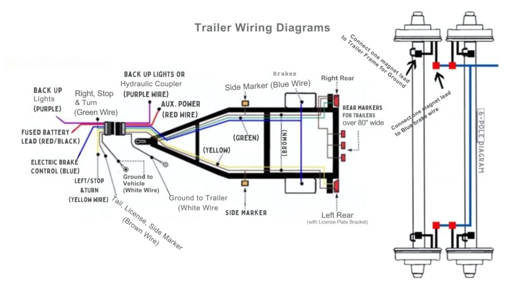
Typical wire color functions are:
- White: Ground
- Blue: Electric Brakes
- Brown: Tail lights, side marker lights, license plate light
- Yellow: Left turn signal and stop light
- Green: Right turn signal and stop light
- Red: Auxiliary power (often for charging a trailer battery)
- Black: 12V power from the tow vehicle battery
Important: Always refer to the specific wiring diagram for your trailer and tow vehicle to confirm the correct wire functions. Color codes can vary, especially with aftermarket installations.
How Electric Trailer Brakes Work – The Detailed Explanation
Here's the sequence of events:
- The Driver Applies the Brakes: When the driver of the tow vehicle applies the brakes, the brake controller senses the deceleration. This is typically done using an inertia sensor or an accelerometer within the controller.
- Brake Controller Activation: The brake controller then sends a variable voltage signal to the blue wire of the trailer connector. The amount of voltage sent is proportional to the deceleration rate of the tow vehicle. A more aggressive braking action results in a higher voltage signal.
- Electromagnet Activation: The voltage signal travels through the trailer wiring to the electromagnets in the brake assemblies. The electromagnets are coils of wire wrapped around a metal core. When voltage is applied, the core becomes magnetized.
- Brake Shoe Activation: The energized electromagnet is drawn towards the rotating brake drum or rotor. This mechanical action forces the brake shoes against the inside of the drum or the surface of the rotor, creating friction.
- Trailer Slows Down: The friction between the brake shoes and the drum/rotor slows down the trailer wheels, helping the tow vehicle to stop safely. The braking force applied to the trailer is proportional to the voltage applied by the brake controller.
- Breakaway Switch Activation (Emergency): In the event of trailer separation, the breakaway switch activates. The cable connecting the switch to the tow vehicle is pulled, completing a circuit that sends full 12V power directly to the trailer brake magnets. This locks the trailer brakes, preventing the trailer from rolling away.
Real-World Use – Basic Troubleshooting Tips
Here are some common troubleshooting scenarios and how to approach them using the wiring diagram:
- No Trailer Brakes: Check the following:
- Brake Controller: Verify the brake controller is properly installed and functioning. Check the power supply and ground connections to the controller. Some controllers have self-diagnostic features.
- Trailer Connector: Inspect the trailer connector and tow vehicle connector for corrosion or damaged pins. Clean the connectors with electrical contact cleaner.
- Wiring: Use a multimeter to check for voltage at the blue wire of the trailer connector when the brake controller is activated. Trace the wiring from the connector to the brake assemblies, checking for breaks or shorts.
- Magnets: Check the resistance of each electromagnet using a multimeter. An open circuit indicates a faulty magnet. (Resistance values vary; consult the magnet's specs).
- Grounds: Ensure all ground connections are clean and secure. A poor ground can cause all sorts of electrical problems.
- One Brake Not Working: The problem is likely isolated to the brake assembly itself or the wiring leading to it. Check the wiring to that particular magnet and the magnet's resistance.
- Brakes Locking Up: This could be caused by a faulty brake controller sending too much voltage or a short circuit in the wiring. Check the controller's output voltage and inspect the wiring for damage. Also, ensure the brake assemblies are properly adjusted.
- Breakaway Switch Problems: If the breakaway switch is constantly activating the brakes, check the switch for damage and ensure the cable is properly connected. A corroded or damaged switch can cause false activations.
Using a Multimeter: A multimeter is your best friend for diagnosing electrical problems. Learn how to use it to check voltage, continuity, and resistance. Remember to always disconnect the power before working on electrical components.
Test Light: An alternative tool is a simple test light. Connect the clip to a good ground and probe the wires. If the light illuminates, there's power. This is a quick way to check for voltage but doesn't provide as much detailed information as a multimeter.
Safety – Risky Components
Working with electrical systems can be dangerous. Here are some critical safety considerations:
- Battery Disconnect: Always disconnect the battery before working on the electrical system. This prevents accidental shorts and electrical shocks.
- Capacitors: Brake controllers and other electronic components may contain capacitors that can store a charge even after the power is disconnected. Discharge capacitors before handling them.
- Wiring: Use appropriately sized wiring for the circuit. Undersized wiring can overheat and cause a fire.
- Fuses: Replace blown fuses with the correct amperage rating. Using a higher amperage fuse can overload the circuit and cause damage.
- Brake Fluid: If you're working on hydraulic brake components (some trailer brakes use a hydraulic actuator linked to the electric system), be careful handling brake fluid. It can damage paint and is harmful if ingested.
- Certified Mechanic: If you're not comfortable working on electrical systems, consult a qualified mechanic. Trailer brakes are critical for safety, and a mistake can have serious consequences.
Brake Controller Output: Be extremely careful testing the brake controller output. Never short the blue wire to ground, as this can damage the controller. Use a multimeter to measure the voltage and amperage.
Remember that working on your own trailer's braking system means you're taking responsibility for its safety. If you're unsure about any aspect of the process, seek professional help. Your safety, and the safety of those around you, is paramount.
You now have a better understanding of how electric trailer brakes operate and the wiring diagram. This detailed knowledge will help keep you and your trailer safe.