How To Identify Short Circuit In A Circuit Diagram
Alright, let's talk about circuit diagrams and how to spot those pesky short circuits. Understanding this is crucial whether you're diagnosing electrical problems in your car, planning a modification, or just generally tinkering with automotive electrics. Think of a circuit diagram as the roadmap to your car's electrical system. Being able to read it and understand it empowers you to troubleshoot issues yourself, saving you time and money at the shop.
Purpose of a Circuit Diagram
Why bother with a circuit diagram? Simple: it's the key to understanding the flow of electricity within a system. They're invaluable for:
- Troubleshooting Electrical Problems: Identifying the source of a problem like a blown fuse, malfunctioning light, or parasitic draw.
- Planning Modifications: Safely and effectively adding aftermarket components like lights, stereos, or performance upgrades.
- Understanding System Operation: Learning how different components interact and how the overall system functions.
- Performing Repairs: Guiding you through component replacement and wire repairs, ensuring you reconnect things correctly.
Without a circuit diagram, you're basically poking around in the dark, hoping to stumble upon the problem. With one, you can systematically trace the circuit and pinpoint the fault.
Key Specs and Main Parts
Before we dive into short circuits, let's cover the basic building blocks of a circuit diagram.
- Voltage Source: Typically, the battery. Represented by a symbol indicating DC voltage (often a long and short parallel line). The voltage rating (e.g., 12V) is usually specified.
- Ground: The reference point for the circuit, typically the car's chassis. Shown as a series of horizontal lines decreasing in length. A solid and reliable ground connection is vital for proper circuit operation.
- Wires: Represented by solid lines. Their color is often indicated next to the line using abbreviations (e.g., BK for black, RD for red, BL for blue). Wire gauge (thickness) might be specified for critical circuits.
- Fuses and Circuit Breakers: Safety devices designed to protect the circuit from overcurrent. Fuses are usually drawn as a squiggly line inside a rectangle, while circuit breakers might have a slightly different symbol. Their current rating (e.g., 10A, 20A) is always marked.
- Switches: Control the flow of current. Represented by various symbols depending on their type (e.g., SPST, SPDT, DPDT).
- Relays: Electrically operated switches. They allow a low-current circuit to control a high-current circuit. Symbols usually include a coil and a set of contacts.
- Loads: Devices that consume electrical energy. Examples include light bulbs, motors, solenoids, and electronic control units (ECUs). Each component has a certain resistance. Resistance opposes the flow of current, and is measured in ohms.
- Connectors: Represented by circles or other symbols at the point where wires join together. They can be a source of problems if corroded or damaged.
Symbols Explained: Decoding the Diagram
Understanding the symbols is critical to reading the diagram. Let's break down some common ones:
- Lines: Solid lines represent wires. Dashed lines might indicate shielded wires or data connections. The *thickness* of the line does not typically represent the wire gauge, although it can be used on complex schematics to differentiate main power wires.
- Colors: Wire colors are *extremely* important for tracing circuits in the real world. Make sure you have a good color key available. Common abbreviations include:
- BK: Black
- RD: Red
- BL: Blue
- GN: Green
- YW: Yellow
- WH: White
- Icons: These vary depending on the manufacturer, but generally follow industry standards. Look for keys or legends on the diagram itself to identify unfamiliar symbols.
How It Works: The Path of Electricity
A circuit diagram shows the complete path that electricity takes from the voltage source (battery) to the load (e.g., light bulb) and back to ground. Electricity flows from the positive terminal of the battery, through the circuit components, and back to the negative terminal (ground). A complete circuit is required for the load to operate.
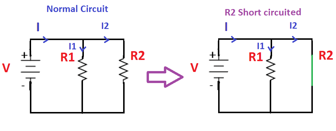
Short Circuit Defined: A short circuit occurs when the intended path of electricity is bypassed, creating a low-resistance path directly back to the source, avoiding all or part of the load. This results in a high current flow, which can damage components, melt wires, and even cause fires.
On the diagram, a short circuit looks like a direct connection from a point in the circuit (usually before the load) to ground. Imagine a wire accidentally touching the chassis. That's a short circuit.
Real-World Use: Basic Troubleshooting Tips
Here's how to use a circuit diagram to find a short circuit:
- Identify the Affected Circuit: What's not working? What fuse keeps blowing? Consult the fuse box diagram to identify the circuit in question.
- Locate the Circuit Diagram: This is where having access to a good service manual or online resource is critical. We can provide you with the circuit diagram for your specific vehicle if needed.
- Visually Inspect the Wiring: Look for obvious signs of damage, such as frayed wires, melted insulation, or corrosion. Pay close attention to areas where wires pass through metal panels or near moving parts.
- Use a Multimeter: A multimeter can be your best friend.
- Continuity Test: Disconnect the battery. Then, use the multimeter to check for continuity between the wire suspected of being shorted and ground. If there's continuity, you've likely found the short circuit.
- Voltage Drop Test: With the circuit powered and operating (if possible), measure the voltage drop across different sections of the wiring. A significant voltage drop indicates a problem, such as a corroded connection or a short circuit.
- Resistance Test: To check for continuity between the wire and ground, set multimeter to OHMs, connect the leads to wire and ground. The meter will show near zero if there is a short circuit.
- Isolate the Problem: Disconnect connectors along the circuit path to isolate the section where the short circuit is located. Once you've narrowed it down, you can focus your attention on that area.
Safety: Handling Risky Components
Working with automotive electrical systems can be dangerous. Always:
- Disconnect the Battery: Before working on any electrical circuit, disconnect the negative terminal of the battery to prevent accidental shocks or short circuits.
- Use Proper Tools: Use insulated tools designed for automotive electrical work.
- Be Careful Around Airbags: Airbag systems are particularly sensitive and can be triggered by electrical shorts. Follow the manufacturer's instructions carefully when working near airbags.
- Handle ECUs with Care: Electronic control units (ECUs) are sensitive to static electricity. Ground yourself before touching them to prevent damage.
Special Note: When working with electrical components near the fuel system, ensure there are no fuel leaks. A spark from a short circuit can ignite fuel vapors.
Fuses: Always replace a blown fuse with one of the same amperage rating. Using a higher amperage fuse can overload the circuit and cause a fire.
By carefully examining the circuit diagram and using the proper troubleshooting techniques, you can confidently identify and repair short circuits in your car's electrical system. Remember to always prioritize safety and take your time.
We have the circuit diagrams for many vehicles in our database. If you need a diagram for your specific car, please provide the year, make, and model, and we can make it available for download.