
How To Put On A Serpentine Belt Diagram
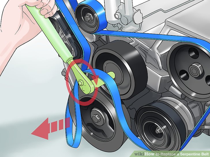
The serpentine belt diagram – it's not just a pretty picture under the hood. It's your roadmap to understanding, maintaining, and troubleshooting one of the most vital systems in your vehicle. Whether you’re tackling a squealing belt, replacing a failing component, or just trying to wrap your head around how your engine accessories are driven, that diagram is your best friend. In this article, we'll delve deep into the world of serpentine belt diagrams, breaking down their purpose, key elements, and how to use them effectively. We are going to talk about why it is important for repairs, car building and general knowlede.
Purpose: Why You Need to Understand the Serpentine Belt Diagram
Think of the serpentine belt diagram as the blueprint for your engine's accessory drive system. Here's why it matters:
- Repairs and Maintenance: The most obvious use. When a serpentine belt breaks, cracks, or squeals, the diagram shows you precisely how to route the new belt correctly. Incorrect routing can damage components and lead to premature belt failure.
- Component Replacement: Replacing components like the alternator, power steering pump, AC compressor, or idler pulley requires removing and reinstalling the serpentine belt. The diagram ensures you put it back exactly as it was.
- Troubleshooting: A misaligned belt, a seized pulley, or a failing tensioner can all be diagnosed with the help of the diagram. You can visually inspect the belt's path and identify potential problem areas.
- Learning and Understanding: Even if you're not actively working on your car, understanding the serpentine belt system deepens your knowledge of automotive mechanics. It lets you appreciate how different components work together.
- Customization and Modification: If you're modifying your engine or adding aftermarket accessories, the diagram becomes invaluable for planning belt routing and ensuring proper function. Maybe you are adding a supercharger or changing to an electric power steering setup. Knowing the original routing will help ensure that the right length belt is selected for your changes.
Key Specs and Main Parts
Before diving into the diagram itself, let's identify the key components within the serpentine belt system:
- Crankshaft Pulley (Harmonic Balancer): Driven directly by the engine, this pulley is the heart of the system, providing rotational force to the belt. This pulley is located on the crankshaft.
- Alternator: Generates electricity to power the car's electrical system and charge the battery. You will find the alternator near the top of the engine.
- Power Steering Pump: Provides hydraulic pressure to assist steering. This can be mounted low on the driver's side of the engine.
- Air Conditioning (AC) Compressor: Compresses refrigerant for the air conditioning system. Look for this toward the front of the engine.
- Idler Pulley: A smooth pulley that guides the belt around other components, ensuring proper wrap angle and tension. There can be multiple idler pulleys, and they are often located in areas with complex routing.
- Tensioner Pulley: Maintains proper belt tension, preventing slippage and ensuring optimal performance. A spring-loaded arm pushes the pulley against the belt.
- Water Pump: Circulates coolant throughout the engine to regulate temperature. Sometimes driven by the serpentine belt.
- Serpentine Belt: A single, continuous belt that drives all the accessories. Made of reinforced rubber. The belt will generally be a standard width depending on the engine size.
Key Specs:
- Belt Length: Measured in inches or millimeters. Critical for proper fit and tension.
- Belt Width: Standardized based on engine application.
- Rib Count: The number of grooves on the belt that match the pulleys.
- Tension: Specified in foot-pounds or Newton-meters. Measured with a specialized tool.
Symbols: Deciphering the Serpentine Belt Diagram
Serpentine belt diagrams use a standardized set of symbols to represent different components and belt routing. Understanding these symbols is crucial for interpreting the diagram correctly:
- Solid Line: Represents the path of the serpentine belt on the grooved side. This is the side that engages with the pulleys, transferring rotational force.
- Dashed Line: Represents the path of the backside (smooth side) of the belt. Usually over an idler pulley.
- Circles: Represent pulleys. The circles are normally labelled with what they are to prevent confusion.
- Arrows: Indicate the direction of belt rotation on each pulley. This is very important to confirm.
- Component Labels: Abbreviations or full names of each component (e.g., ALT for alternator, AC for air conditioning compressor, PS for power steering). The key can be in the diagram or in a reference sheet for that engine.
- Tensioner Symbol: A special symbol indicates the location and type of tensioner (spring-loaded, hydraulic, etc.). The tensioner might be drawn in multiple positions to indicate its full range of motion.
- Routing Markers: Sometimes, numbers or letters are placed along the belt path to indicate the correct order of routing.
- Color Coding: Some diagrams use colors to highlight specific sections of the belt path or to distinguish between different belt types. While not standardized, these color codings are often noted in the diagrams to help the user.
How It Works: The Serpentine Belt System in Action
The serpentine belt system is a relatively simple yet ingenious design. The engine's crankshaft drives the crankshaft pulley. This pulley, in turn, drives the serpentine belt, which snakes its way around all the other accessory pulleys. The tensioner pulley maintains the correct belt tension, preventing slippage and ensuring that all accessories are driven efficiently. The serpentine belt is made out of rubber, so it is important that the tensioner pulley is functioning correctly.
The key to the system's effectiveness is the serpentine belt's single, continuous design. This eliminates the need for multiple belts, simplifying maintenance and reducing the risk of belt failure.
Important Notes:
- The belt must be routed exactly as shown in the diagram. Incorrect routing can cause damage to components and premature belt failure.
- The belt tension must be correct. Too loose, and the belt will slip. Too tight, and it can damage bearings and wear out quickly.
- Regular inspection of the belt and pulleys is essential for preventing breakdowns.
Real-World Use: Basic Troubleshooting Tips
Here's how to use the serpentine belt diagram in common troubleshooting scenarios:
- Squealing Belt: Check the belt tension. If the belt is loose, adjust the tensioner. If the belt is old or cracked, replace it. Use the diagram to ensure proper routing.
- Broken Belt: Inspect all pulleys for signs of damage or seizure. Replace any damaged components before installing a new belt. Route the new belt according to the diagram.
- Accessory Failure: If an accessory isn't working (e.g., the AC compressor isn't engaging), check the belt routing and tension. A slipping belt could be the cause. The diagram can help you quickly identify the relevant pulley and belt path.
- Belt Alignment Issues: A misaligned pulley can cause the belt to wear prematurely or even jump off. Use a straight edge or laser alignment tool to check the alignment of all pulleys, referencing the diagram to ensure they are properly positioned.
- Belt Noise: Check the pulleys. Spin the pulleys to check for noise or roughness. Replace any defective pulleys.
Safety: Important Precautions
Working with the serpentine belt system can be dangerous if you're not careful. Here are some essential safety precautions:
- Disconnect the Battery: Before working on any part of the system, disconnect the negative battery cable to prevent accidental starts.
- Hot Engine: Never work on the system when the engine is hot. Allow the engine to cool completely before beginning any repairs.
- Moving Parts: Be extremely careful around moving parts. Keep your hands, tools, and clothing away from the belt and pulleys when the engine is running.
- Sharp Edges: The edges of the pulleys and belt can be sharp. Wear gloves to protect your hands.
- Tensioner Springs: Be cautious when releasing the tension on the tensioner pulley. The spring can be very strong and can cause injury.
Highlighting Risky Components:
- The Tensioner Pulley: This is spring-loaded and can snap back with considerable force. Use appropriate tools to safely release the tension.
- The Crankshaft Pulley: Directly connected to the engine, it rotates at high speed. Keep your hands and tools well clear when the engine is running.
Understanding and using a serpentine belt diagram is a fundamental skill for any DIY mechanic or car enthusiast. It empowers you to maintain, troubleshoot, and repair your engine's accessory drive system with confidence.
This article provides a general overview. Always refer to the specific serpentine belt diagram for your vehicle's make and model for the most accurate information. With practice and attention to detail, you'll be able to tackle serpentine belt-related tasks like a pro!
We have a file with several serpentine belt diagrams for common vehicles available for download. Contact us for access.