
How To Read A Electrical Wiring Diagram
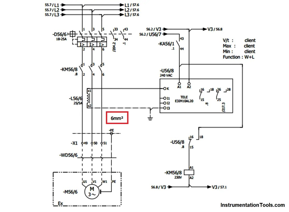
So, you're ready to tackle some electrical work on your ride? Smart move. But before you dive in, you're going to need a good electrical wiring diagram. Think of it as the roadmap for your car's entire electrical system. Forget guessing which wire does what – a diagram will tell you exactly what's connected where, saving you time, frustration, and potentially a fried ECU (Engine Control Unit).
Why Bother with a Wiring Diagram?
Let's be honest, electrical problems can be a nightmare. They're often intermittent, and tracking down the root cause can feel like searching for a needle in a haystack. That's where a wiring diagram shines. Its primary purpose is to provide a visual representation of the electrical circuits in your vehicle. This allows you to:
- Troubleshoot Electrical Issues: Pinpoint shorts, opens, and other faults quickly.
- Perform Repairs: Ensure you're connecting wires correctly after replacing components.
- Install Aftermarket Accessories: Wire up that new stereo, alarm system, or lighting setup with confidence.
- Understand Your Vehicle's Electrical System: Gain a deeper understanding of how everything works together.
- Customize/Modify: Safely make modifications to the electrical system for performance or aesthetic enhancements.
Trying to troubleshoot or modify your car's electrical system without a diagram is like navigating a city without a map – you're likely to get lost (and potentially damage something important). It's simply not worth the risk.
Key Specs and Main Parts of a Wiring Diagram
Before we decode the symbols, let's look at the key components and terms you'll encounter:
- Power Source: Usually the battery, represented by a symbol resembling a set of parallel lines (one long, one short). Look for voltage ratings (e.g., 12V).
- Ground: The return path for current, typically represented by a series of horizontal lines getting progressively shorter, or a triangle pointing downwards.
- Wires: Solid lines connecting components. Their color is usually indicated (e.g., BLU for blue, GRN for green). Wire gauge (thickness) might also be specified, affecting current carrying capacity.
- Fuses and Circuit Breakers: Protection devices that interrupt the circuit if the current exceeds a safe level. Fuses are often represented by a squiggly line within a rectangle, while circuit breakers may have a switch-like symbol. Never bypass a fuse!
- Relays: Electrically operated switches that allow a low-current circuit to control a high-current circuit. They're typically represented by a coil symbol and a switch symbol.
- Switches: Devices that open or close a circuit. Different types of switches (e.g., single-pole single-throw [SPST], single-pole double-throw [SPDT]) have distinct symbols.
- Connectors: Points where wires are joined together. Often represented by circles or squares.
- Components: These are the devices being powered or controlled, such as lights, motors, sensors, and control modules (ECU, BCM – Body Control Module, etc.). Each component has its own specific symbol.
Decoding the Symbols: Lines, Colors, and Icons
This is where the magic happens. Understanding the symbols is crucial for interpreting the diagram.
Lines: The Electrical Highways
- Solid Lines: Represent wires. Thicker lines may indicate higher current carrying capacity.
- Dashed Lines: Can represent shielded wires, ground wires, or connections that are optional or only present in specific vehicle configurations. Always check the diagram's legend!
- Arrows: Indicate the direction of current flow (though conventional current flow is often assumed).
Colors: Identifying Wires at a Glance
Wire colors are typically abbreviated using a standardized set of codes. Here are some common ones:
- BLK or BK: Black
- RED or RD: Red
- BLU or BU: Blue
- GRN or GN: Green
- YEL or YE: Yellow
- WHT or WH: White
- BRN or BN: Brown
- ORG or OR: Orange
- PPL or PU: Purple
- GRY or GY: Gray
Sometimes, you'll see two-color codes (e.g., BLU/WHT). This means a blue wire with a white stripe.
Icons: Representing Components
Each electrical component has a specific symbol. While memorizing them all is impossible, understanding the general principles will help:
- Resistors: Represented by a zig-zag line.
- Capacitors: Represented by two parallel lines (sometimes curved).
- Diodes: Represented by a triangle pointing to a line. The triangle indicates the direction of allowed current flow.
- Transistors: More complex symbols, but generally involve a base, collector, and emitter.
- Motors: Usually a circle with an "M" inside.
- Lights: Resemble a circle with a cross inside.
- Sensors: Symbols vary depending on the type of sensor, but often include a square or rectangle with an arrow or other indicator.
Always refer to the diagram's legend. This is a critical part of the document that provides a key to all the symbols used.
How It Works: Tracing the Circuit
Reading a wiring diagram involves tracing the flow of electricity through the circuit. Start at the power source (battery) and follow the wires. Look for switches, relays, fuses, and other components along the way. Pay attention to the wire colors and connector locations.
For example, if you're troubleshooting a faulty headlight, you would start by locating the headlight circuit on the diagram. Then, you'd trace the circuit back to the battery, identifying all the components in the path (e.g., the headlight switch, the headlight relay, the fuse). By systematically checking each component, you can isolate the problem.
Real-World Use: Basic Troubleshooting Tips
Here are a few basic troubleshooting techniques you can use with a wiring diagram:
- Voltage Drop Testing: Use a multimeter to measure the voltage drop across different points in the circuit. A high voltage drop indicates resistance, which could be caused by a corroded connection or a faulty wire.
- Continuity Testing: Use a multimeter to check for continuity between two points in the circuit. A lack of continuity indicates an open circuit.
- Ground Testing: Verify that the ground connections are solid. A poor ground can cause all sorts of electrical problems.
- Component Isolation: Disconnect components one at a time to see if the problem goes away. This can help you narrow down the source of the fault.
Important: Always disconnect the battery's negative terminal before working on the electrical system to prevent accidental shorts.
Safety First: Risky Components
Some electrical components can be dangerous if handled improperly. These include:
- The Battery: Contains acid and can produce explosive gases. Always wear safety glasses and gloves when working around the battery.
- High-Voltage Systems: Some vehicles (especially hybrids and electric vehicles) have high-voltage systems that can be lethal. Never attempt to work on these systems unless you are properly trained and equipped.
- Airbag System: The airbag system is sensitive to static electricity and can deploy unexpectedly. Disconnect the battery and wait several minutes before working near the airbags.
If you are unsure about any aspect of the electrical system, consult a qualified mechanic.
Electrical wiring diagrams may seem daunting, but with practice and a good understanding of the basics, you can use them to diagnose and repair electrical problems, install aftermarket accessories, and gain a deeper understanding of your vehicle's electrical system. Remember to take your time, be careful, and always prioritize safety. Working methodically and using your diagram as a guide, you'll be surprised at what you can accomplish.
You can download the sample electrical wiring diagram to get a better grasp of the concepts discussed here. Just click the download link below.
Download Electrical Wiring Diagram (PDF)