
How To Read A Schematic Wiring Diagram
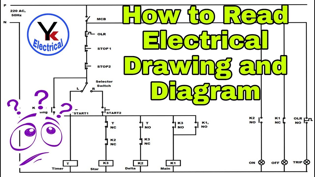
So, you're ready to dive into the world of automotive wiring diagrams? Excellent! Think of these diagrams as the blueprints of your car's electrical system. Understanding them empowers you to diagnose problems, perform modifications with confidence, and truly understand how your vehicle ticks. Whether you're chasing down a parasitic draw, installing aftermarket accessories, or just trying to learn more about your car, knowing how to read a schematic wiring diagram is an invaluable skill.
Why Bother with Wiring Diagrams?
The purpose of a wiring diagram goes far beyond simply looking pretty on paper (or a screen). They are essential for:
- Troubleshooting: Pinpointing the exact location of a short, open circuit, or voltage drop. Imagine trying to find a broken wire in a complex harness without a map – impossible!
- Repairs: Confirming connections after replacing components, ensuring you haven't accidentally introduced new issues.
- Modifications: Safely and correctly adding new electrical components like lights, stereos, or performance upgrades. A poorly wired modification can cause serious damage.
- Understanding Vehicle Systems: Gaining a deeper understanding of how different systems interact and how sensors and actuators are controlled.
- Preventing Damage: Correct wiring helps prevent shorts, fires, and damage to sensitive electronic components like the ECU (Engine Control Unit).
Key Specs and Main Parts of a Wiring Diagram
Before we dive into the symbols and lines, let's establish some fundamental concepts.
- Components: These are the actual physical devices in your car's electrical system, like headlights, sensors, relays, motors, and fuses.
- Wires: The conductors that carry electricity between components.
- Connectors: Points where wires join together, often using plugs or terminals. These are frequently the source of corrosion and problems.
- Grounds: Connection points to the vehicle's chassis, providing a return path for current. A good ground is essential for proper circuit operation.
- Power Source: Typically the battery, alternator, or ignition switch providing the voltage needed to operate the circuit.
- Fuses/Circuit Breakers: Safety devices that protect the circuit from overcurrent.
Key Specs you might find include:
- Wire Gauge: The thickness of the wire, usually measured in American Wire Gauge (AWG). Thicker wires can carry more current.
- Voltage: The electrical potential of the circuit (typically 12V in automotive applications).
- Current Rating (Amps): The maximum current the wire or component can safely handle.
Decoding the Symbols: Lines, Colors, and Icons
This is where the magic happens! Wiring diagrams use a standardized set of symbols to represent different components and connections. Understanding these symbols is crucial for interpreting the diagram. While symbols can vary slightly between manufacturers, here are some common ones:
Lines and Colors:
- Solid Lines: Represent wires connecting components. The thickness of the line does *not* usually indicate wire gauge, though some advanced diagrams may use it to highlight important circuits.
- Dashed Lines: Often represent shielded cables or connections that are part of a larger harness. Sometimes show a shared ground connection.
- Wire Colors: One of the most important clues! Each wire is assigned a color code (e.g., "RD/BK" for Red with a Black stripe). Always use the wiring diagram for *your specific year and model* car, as colors can change.
Component Icons (Examples):
These are just a few examples; refer to the legend on *your* specific diagram for a complete list.
- Resistor: Zigzag line.
- Capacitor: Two parallel lines.
- Diode: Triangle pointing to a line.
- Transistor: Circle with three leads.
- Relay: Coil symbol connected to a switch.
- Fuse: A line with a break, often shaped like an "S".
- Switch: A break in the line that can be opened or closed.
- Ground: Several common symbols exist, often resembling an upside-down triangle or a series of stacked lines getting smaller.
- Battery: Alternating long and short parallel lines.
- Light Bulb: A circle with an "X" inside.
- Motor: Circle with an "M" inside.
Also pay close attention to connector symbols! They usually consist of a box or circle, often with a number indicating the number of pins in the connector. Knowing connector locations is essential for physical troubleshooting.
How It Works: Following the Flow of Electricity
Wiring diagrams are designed to show the path of electricity from the power source (battery, alternator) through the components and back to ground. The diagram typically shows the circuit in its *normal*, *unenergized* state (e.g., ignition off). Here's a simplified breakdown:
- Identify the Power Source: Look for the battery symbol, ignition switch, or other power supply.
- Trace the Path: Follow the solid lines from the power source, noting the wire colors and components along the way.
- Identify Switches and Relays: Understand how these devices control the flow of electricity. A switch, when closed, completes the circuit; a relay uses a small current to control a larger current in another circuit.
- Find the Load: The "load" is the component that consumes power (e.g., a light bulb, motor, or solenoid).
- Locate the Ground: The circuit must have a path back to ground for electricity to flow. Ensure you can identify all the ground points in the circuit.
Real-World Use: Basic Troubleshooting Tips
Now that you understand the basics, let's apply this knowledge to troubleshooting a common problem: a headlight that doesn't work.
- Consult the Wiring Diagram: Locate the headlight circuit for your car model.
- Check the Fuse: The diagram will show the fuse location. Use a multimeter or test light to confirm the fuse is good. If the fuse is blown, replace it and see if it blows again. If it does, there's a short circuit somewhere.
- Test the Bulb: Visually inspect the bulb and test it with a multimeter.
- Check the Connector: Inspect the headlight connector for corrosion or loose connections.
- Trace the Wiring: Using the diagram, trace the wiring from the fuse to the headlight. Look for any breaks, damage, or shorts to ground.
- Test for Voltage: Use a multimeter to check for voltage at the headlight connector. If there's no voltage, trace back towards the fuse, checking for voltage at each connection point.
- Check the Ground: A bad ground is a common culprit. Ensure the ground connection is clean and tight.
Remember to always work methodically and document your findings!
Safety First: Handle with Care!
Working with automotive electrical systems can be dangerous. Here are some key safety precautions:
- Disconnect the Battery: Always disconnect the negative battery terminal before working on the electrical system to prevent shorts and shocks.
- Use Proper Tools: Use insulated tools designed for electrical work.
- Be Aware of High-Voltage Components: Some components, like the ignition system and hybrid/electric vehicle components, can carry high voltages. Do not attempt to work on these systems unless you are properly trained and equipped.
- Avoid Water: Never work on electrical systems in wet conditions.
- Double-Check Your Work: Before reconnecting the battery, double-check all connections and wiring to ensure everything is correct.
Special Note: Components like the airbag system and ABS (Anti-lock Braking System) are extremely sensitive. Mishandling can cause them to deploy unexpectedly, leading to serious injury. If you're not comfortable working on these systems, leave them to a qualified professional.
Understanding wiring diagrams takes practice, but it's a skill that will pay off handsomely. Start with simple circuits and gradually work your way up to more complex systems. With a little patience and the right resources, you'll be diagnosing and repairing electrical problems like a pro in no time!
And to help you get started, we have a sample schematic wiring diagram file available for download. Dive in and start practicing!