
How To Read A Wiring Diagram For A Car
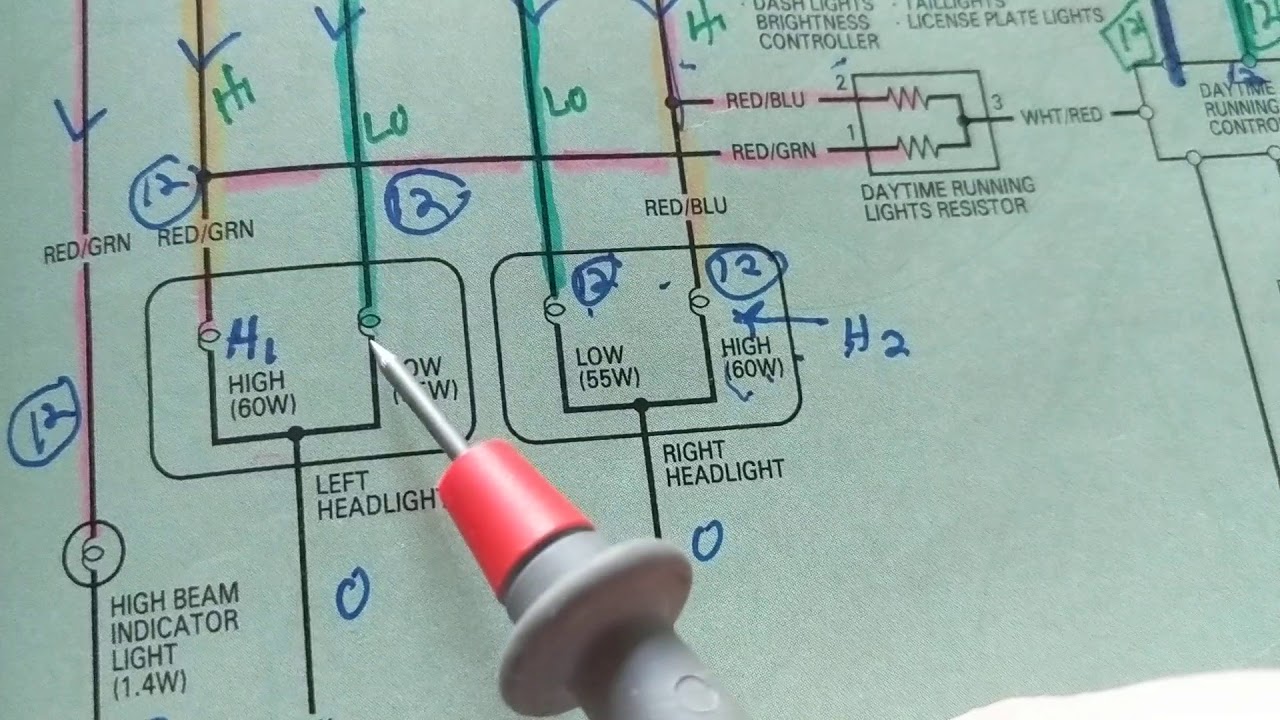
Alright, let's dive into the world of automotive wiring diagrams. These diagrams might look like a jumbled mess of lines and symbols at first glance, but trust me, once you understand the basics, they become invaluable tools for diagnosing electrical problems, performing modifications, or simply understanding how your car's electrical system works. We’ve got the wiring diagram for your vehicle ready for download; more on that later.
Purpose of Wiring Diagrams
Why bother learning to read a wiring diagram? The answer is simple: control. With a good understanding of the diagram, you're no longer at the mercy of guesswork when tackling electrical issues. It empowers you to:
- Diagnose Electrical Faults: Quickly pinpoint shorts, opens, and other electrical problems.
- Perform Modifications: Safely add aftermarket accessories like lights, stereos, or remote starters.
- Understand System Operation: Gain a deeper understanding of how different components interact.
- Avoid Costly Repairs: Repair electrical issues yourself instead of paying a mechanic.
Think of a wiring diagram as a roadmap for your car's electrical system. Just as a map guides you through unfamiliar terrain, a wiring diagram guides you through the complex network of wires, components, and connections within your vehicle.
Key Specifications and Main Parts
Before we delve into the symbols, let's define some key specifications and parts you'll encounter in nearly every automotive wiring diagram:
- Voltage (V): The electrical potential difference between two points. Typically, in automotive applications, this is 12V (nominally) for standard systems, but higher voltages (48V and above) are becoming more common in hybrid and electric vehicles.
- Current (A): The flow of electrical charge, measured in Amperes (Amps). Knowing the current draw of a circuit is crucial for selecting the correct wire gauge and fuse size.
- Resistance (Ω): The opposition to the flow of current, measured in Ohms. High resistance can indicate a corroded connection or a failing component.
- Ground: The reference point for all voltages in the circuit. Typically, the car's chassis serves as ground. A good ground connection is critical for proper circuit operation.
- Power Source: Usually the battery, but can also be the alternator when the engine is running.
- Fuses and Circuit Breakers: Overcurrent protection devices that interrupt the circuit if the current exceeds a safe level, preventing damage and fires.
- Relays: Electrically operated switches that allow a low-current circuit to control a high-current circuit.
- Switches: Devices that open or close a circuit, allowing or preventing current flow.
- Connectors: Points where wires are joined together. They're common source of problems due to corrosion or loose connections.
- Sensors: Devices that measure physical parameters (temperature, pressure, speed, etc.) and convert them into electrical signals.
- Actuators: Devices that convert electrical signals into mechanical motion (e.g., motors, solenoids).
- ECU (Engine Control Unit) / BCM (Body Control Module): The car's computer, responsible for controlling various systems based on sensor inputs and programmed logic.
Symbols: Deciphering the Code
The heart of any wiring diagram is its collection of symbols. Let's break down the common ones:
Lines: The Pathways
- Solid Lines: Represent wires. The thickness of the line usually does not indicate wire gauge.
- Dashed Lines: Often indicate shielded wires (used for sensitive signals to reduce interference) or wiring that's optional or present only in certain vehicle configurations.
- Lines Crossing: If lines cross without a dot, it means they are not connected. If they cross with a dot, it signifies an electrical connection (solder joint, splice, etc.).
Colors: The Identifiers
Wire colors are crucial for identifying wires in the vehicle. Wiring diagrams use abbreviations for colors, such as:
- BK: Black
- RD: Red
- BL: Blue
- GN: Green
- WT: White
- YL: Yellow
- OR: Orange
- BR: Brown
Often, wires have a primary color and a stripe color (e.g., "WT/BL" means white wire with a blue stripe). These color codes are very important, so get used to referencing them.
Icons: The Components
Wiring diagrams use standardized icons to represent electrical components. Here are some common ones:
- Resistor: A zig-zag line.
- Capacitor: Two parallel lines.
- Inductor: A coil-shaped line.
- Diode: A triangle pointing to a vertical line.
- Transistor: A more complex symbol with three terminals (Base, Collector, Emitter).
- Ground: A series of horizontal lines getting shorter.
- Battery: A long line and a short line in parallel.
- Fuse: A squiggly line inside a rectangle, or a simple rectangle with a number indicating the amperage.
- Relay: A coil and a switch, showing how the coil activates the switch.
- Switch: A line that breaks and connects to another line, often showing different switch positions.
- Motor: A circle with an "M" inside.
- ECU/BCM: A rectangle with pins labeled.
Keep a key or legend handy while you're learning. Most diagrams include a legend that defines all the symbols used.
How It Works: Tracing the Circuit
To understand how a circuit works, start at the power source (usually the battery) and trace the path of the current. Follow the wires through switches, fuses, relays, and other components until you reach the load (e.g., a light bulb, motor, or electronic module). Pay attention to:
- The Switch Position: Is the switch open or closed? This determines whether current can flow.
- The Fuse Rating: Is the fuse the correct size for the circuit? A blown fuse indicates an overcurrent condition.
- The Ground Connection: Is there a good ground connection? A poor ground can cause all sorts of problems.
- Voltage Drops: Use a multimeter to measure the voltage at various points in the circuit. A significant voltage drop indicates resistance in the wiring or a failing component.
Understanding the intended flow of current is crucial for troubleshooting. By comparing the actual behavior of the circuit to the diagram, you can pinpoint the source of the problem.
Real-World Use: Basic Troubleshooting Tips
Let's say your headlights aren't working. Here's how you might use a wiring diagram to troubleshoot the problem:
- Consult the Diagram: Find the wiring diagram for the headlight circuit in your car's repair manual or online.
- Identify Components: Locate the headlight switch, fuses, relays (if any), and the headlights themselves in the diagram.
- Check the Fuses: Use a multimeter to check if the headlight fuse is blown. If so, replace it with a fuse of the correct amperage.
- Test the Switch: Use a multimeter to check if the headlight switch is working properly. Does it provide continuity when switched on?
- Inspect the Wiring: Look for damaged or corroded wires and connectors in the headlight circuit.
- Check the Grounds: Ensure the headlights have a good ground connection.
- Test the Relay: If there's a relay in the headlight circuit, test it to make sure it's working properly.
By systematically checking each component and connection in the circuit, you can narrow down the cause of the problem and fix it.
Safety: Handle with Care
Working with automotive electrical systems can be dangerous. Always disconnect the negative battery cable before working on any electrical circuits. Be especially careful when working with:
- Airbag Systems: Improper handling can cause accidental deployment, leading to serious injury.
- High-Voltage Systems (Hybrids/EVs): These systems can deliver lethal shocks. Only qualified technicians should work on them.
- Fuel Injection Systems: Use caution when working around fuel lines and injectors.
Always use proper safety equipment, such as insulated tools and gloves. If you're unsure about anything, consult a qualified technician.
Remember, electrical systems can be complex, and a small mistake can cause serious damage or injury. Work slowly, carefully, and always double-check your connections. Learning to read wiring diagrams is a skill that takes time and practice, but the rewards are well worth the effort. We have the wiring diagram specific to your vehicle available for download. Look for the link below. With the right knowledge and tools, you can confidently tackle most automotive electrical problems.