How To Read Auto Electrical Diagrams
So, you’re ready to dive deeper into your car's electrical system? Awesome! Understanding auto electrical diagrams is a seriously valuable skill. Forget just changing oil; this is about truly understanding how your machine *works*. This article will equip you to read and interpret these diagrams, empowering you to diagnose problems, perform modifications, and gain a much greater appreciation for the technology humming beneath your hood.
Purpose – Why Bother with Electrical Diagrams?
Let's be honest: modern cars are essentially rolling computers. Their complexity makes troubleshooting even simple issues a nightmare without proper documentation. That's where electrical diagrams come in. Their primary purpose is to provide a visual representation of the entire electrical system, allowing you to:
- Diagnose Electrical Problems: Trace circuits to identify shorts, opens, and voltage drops.
- Perform Repairs: Understand how components are connected to ensure accurate replacements and wiring.
- Plan Modifications: Add aftermarket accessories like lights, stereos, or alarms safely and correctly.
- Understand System Operation: See the big picture of how different components interact.
- Verify repairs: Once a repair is complete, you can reference the diagrams to verify the work.
Trying to troubleshoot electrical problems without a diagram is like navigating a maze blindfolded. You'll be poking around, hoping to get lucky, and likely making things worse. A diagram provides a clear roadmap, significantly reducing wasted time and potential damage.
Key Specs and Main Parts of a Diagram
Before we jump into deciphering symbols, let’s look at the basic elements found in most auto electrical diagrams:
- Power Source: Usually the battery, represented by a symbol depicting a cell or battery pack.
- Ground (Earth): The return path for current, indicated by ground symbols. Crucially, the location of the ground point is often indicated on the diagram, which helps in tracking down grounding issues.
- Wiring Harnesses: Bundles of wires, typically grouped together and identified with specific codes.
- Fuses and Circuit Breakers: Protective devices that prevent overload damage. Their amperage rating is usually specified.
- Relays: Electrically operated switches that control high-current circuits using a low-current signal.
- Switches: Manually operated devices that open or close circuits (e.g., ignition switch, light switch).
- Sensors: Devices that measure physical quantities (temperature, pressure, speed) and convert them into electrical signals.
- Actuators: Devices that convert electrical signals into mechanical actions (e.g., motors, solenoids, injectors).
- Control Modules (ECU, BCM, etc.): Electronic control units that process sensor data and control actuators. These often have multiple input and output pins, and the diagram will show which wires connect to each pin.
Diagrams will also often include voltage values, resistance values, and component locations to further assist in troubleshooting.
Symbols – Decoding the Language of Electrical Diagrams
Understanding the symbols is paramount. Here's a breakdown of common elements:
Lines and Colors:
- Solid Lines: Represent wires carrying current.
- Dashed Lines: Often indicate control lines or shielded wiring.
- Line Thickness: Sometimes indicates wire gauge (thicker lines = larger gauge).
- Colors: Wires are color-coded, and these colors are indicated on the diagram (e.g., Red (R), Blue (B), Green (G), Black (BK)). Referencing the color code is critical.
Common Icons:
Resistor: A jagged line.
Capacitor: Two parallel lines.
Inductor: A coil or series of loops.
Diode: A triangle pointing to a vertical line.
Transistor: Three terminals connected to a central line, with arrows indicating current flow.
Fuse: A squiggly line inside a rectangle or a simple "S" shape.
Relay: A coil with a switch that is activated when the coil is energized.
Ground: Three lines decreasing in length, resembling a triangle pointing downwards.
Beyond these basics, you'll encounter symbols specific to automotive systems, such as those for headlights, taillights, motors, and various sensors. Many diagrams include a legend or key that explains all the symbols used. *Always consult the legend first!*
How It Works: Tracing a Circuit
Reading a diagram involves tracing the flow of current through a circuit. Start at the power source (battery), follow the wire through various components (fuses, switches, relays), and finally to the load (e.g., a light bulb or motor). Then, trace the return path back to ground.
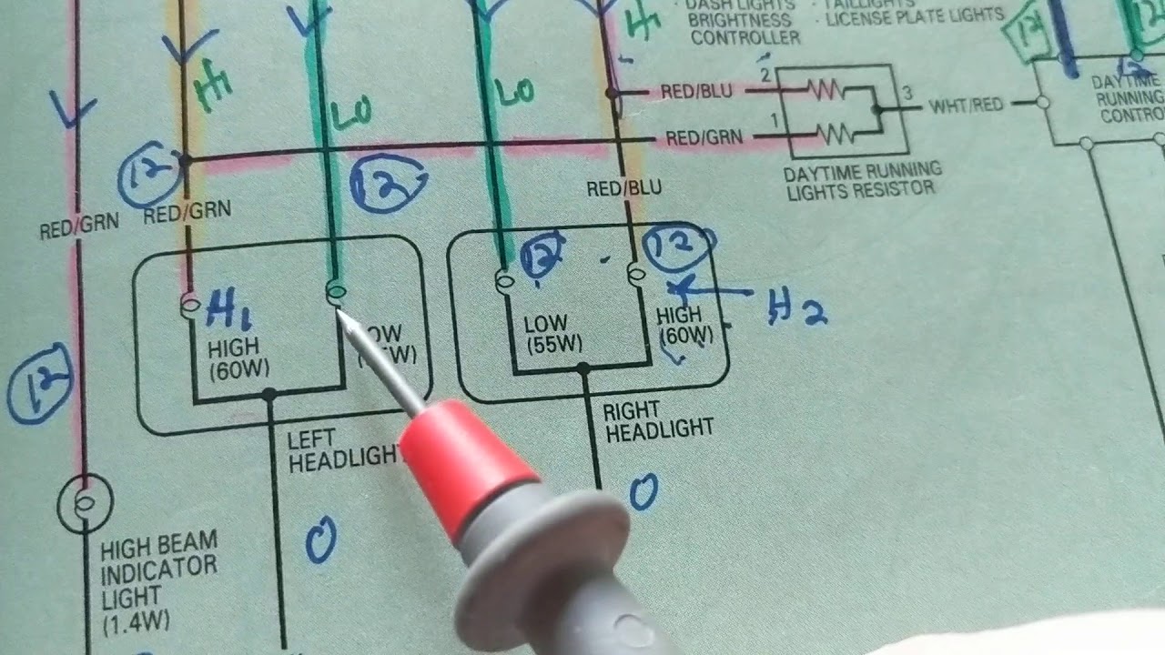
Consider a simple headlight circuit: Current flows from the battery, through a fuse (for protection), through the headlight switch (to control on/off), to the headlight bulb (the load), and then back to ground. If the headlight isn't working, you can use the diagram to systematically check each component:
- Is the fuse blown?
- Is the switch working correctly?
- Is there voltage at the headlight bulb connector?
- Is the ground connection solid?
By systematically checking each point, you can pinpoint the source of the problem.
Real-World Use: Basic Troubleshooting Tips
Here are some basic troubleshooting tips using electrical diagrams:
- Start with the Basics: Check the battery voltage and ground connections first. A weak battery or poor ground can cause all sorts of seemingly unrelated problems.
- Use a Multimeter: A multimeter is your best friend for electrical troubleshooting. Use it to measure voltage, resistance, and current.
- Check for Voltage Drops: A voltage drop indicates resistance in the circuit, which can be caused by corroded connections or damaged wiring.
- Isolate the Problem: Divide the circuit into sections and test each section individually to narrow down the source of the fault.
- Don't Guess: Avoid replacing components randomly. Always test and verify before replacing anything.
- Consult the Diagram Regularly: Keep the diagram handy and refer to it frequently as you work.
Example: Let's say your car's turn signals aren't working. The diagram shows that the turn signal circuit includes a fuse, the turn signal switch, the flasher relay, and the turn signal bulbs. You would start by checking the fuse. If the fuse is good, you would then check the flasher relay. If the relay is good, you would then check the turn signal switch. By following the diagram, you can quickly isolate the problem.
Safety – Respect the Electricity!
Working with electricity can be dangerous. Here are some important safety precautions:
- Disconnect the Battery: Always disconnect the negative battery cable before working on the electrical system to prevent accidental shorts and shocks.
- Be Careful with Airbags: Airbag systems contain explosive charges. Follow the manufacturer's instructions carefully when working near airbags.
- Avoid Working in Wet Conditions: Water conducts electricity, increasing the risk of shock.
- Use Insulated Tools: Use tools with insulated handles to protect yourself from electrical shock.
- Never Bypass Fuses: Fuses are there to protect the circuit from overload. Bypassing a fuse can cause a fire.
- High Voltage Components: Be extremely careful around components like the ignition coil and fuel injectors, as they operate at high voltage.
Remember, if you are not comfortable working with electricity, take your car to a qualified mechanic. Your safety is paramount.
Understanding automotive electrical diagrams is a learning journey. The more you use them, the more proficient you will become. Start with simple circuits and gradually work your way up to more complex systems. And don't be afraid to ask for help from experienced mechanics or online forums.
Now that you're armed with this knowledge, you're ready to start deciphering your vehicle's electrical system. Remember, patience and systematic troubleshooting are key. Happy wrenching!
We have a sample diagram file available for download to help you practice. Click the link below to download.
[Download Sample Auto Electrical Diagram Here]