How To Read Automotive Electrical Wiring Diagrams
Understanding automotive electrical wiring diagrams is an invaluable skill for any serious DIY mechanic, car modder, or even just a conscientious car owner. It empowers you to diagnose electrical problems, safely install aftermarket components, and even perform more complex repairs that would otherwise require a trip to a potentially expensive shop. Think of it as a roadmap to your car's nervous system, allowing you to trace circuits, identify components, and understand how everything is connected.
Purpose: Your Electrical Roadmap
Wiring diagrams serve several critical purposes:
- Troubleshooting Electrical Issues: The primary use is diagnosing electrical faults. By tracing circuits, you can pinpoint shorts, opens, and other problems.
- Installing Aftermarket Components: Whether it's a new stereo, alarm system, or performance upgrade, a wiring diagram ensures you connect it correctly and safely.
- Understanding Vehicle Systems: Even if you're not actively working on the car, the diagram provides insight into how different systems (like the ignition, fuel injection, or lighting) function.
- Performing Repairs: For complex repairs involving electrical components, the diagram is essential for understanding the circuit and ensuring proper reassembly.
- Verification and Validation: Confirming the correctness of modifications or repairs performed by others.
Key Specs and Main Parts of an Automotive Wiring Diagram
Before diving in, let's break down the key elements you'll encounter:
Components:
These represent the physical electrical parts of the car.
- Power Source: Typically the battery, identified by its voltage (e.g., 12V).
- Switches: Devices that open or close circuits (e.g., ignition switch, headlight switch).
- Relays: Electrically operated switches used to control high-current circuits with a low-current signal.
- Fuses/Circuit Breakers: Safety devices that protect circuits from overcurrents. Fuses "blow" (melt) to break the circuit, while circuit breakers "trip" and can be reset.
- Resistors: Components that limit current flow.
- Capacitors: Components that store electrical energy.
- Diodes: Components that allow current to flow in only one direction.
- Sensors: Devices that measure physical parameters (e.g., temperature, pressure) and convert them into electrical signals.
- Actuators: Devices that convert electrical signals into mechanical action (e.g., motors, solenoids).
- Control Modules (ECUs): Electronic Control Units, such as the engine control unit (ECU), that manage various vehicle systems. These are often represented as boxes with input and output connections.
- Grounds: Connection points to the vehicle's chassis, providing a return path for current. Often indicated by the ground symbol.
- Connectors: Physical connectors that join wires together. Diagrams usually show the connector location and pin numbers.
Wiring:
These represent the electrical wires that connect the components.
- Wires: Lines that connect the components, indicating the flow of electrical current.
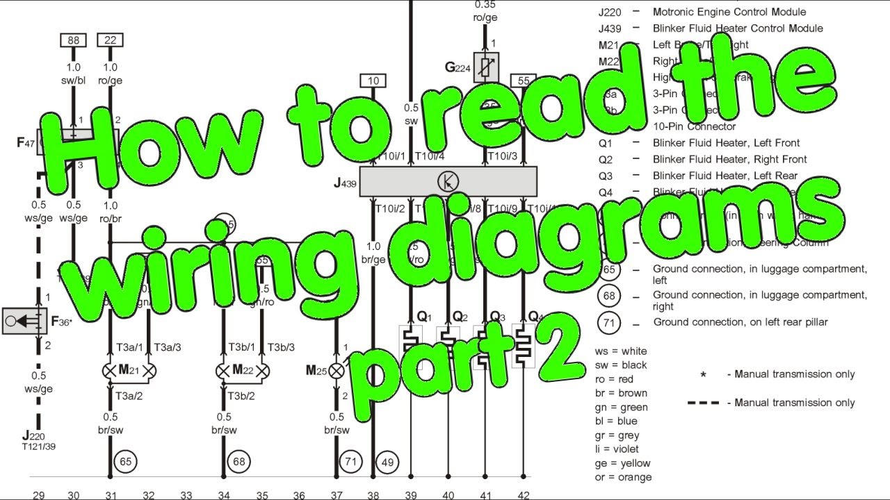
- Wire Colors: Wires are identified by color codes (e.g., "RD" for red, "BL" for blue, "BK" for black). These color codes are crucial for identifying the correct wire in the harness. Some diagrams include a second color stripe, indicated by a slash (e.g., "RD/BK" for red with a black stripe).
- Wire Gauge: Indicates the wire's thickness (e.g., 18 AWG, 14 AWG). Thicker wires can carry more current.
- Splices: Points where multiple wires are joined together.
Diagram Format:
How the information is organized on the page.
- Circuit Tracing: The ability to follow a circuit from its power source to its ground.
- Component Identification: Clearly labeled components with their corresponding symbols.
- Connector Locations: Information on where to find the physical connectors in the vehicle.
- Ground Point Locations: The specific spot on the chassis where a ground wire is attached.
- Page References: If a circuit continues onto another page, the diagram will indicate the corresponding page number.
Symbols: The Language of Wiring Diagrams
Understanding the symbols used in wiring diagrams is essential for accurate interpretation. Here's a breakdown of common symbols:
- Lines: Represent wires. Solid lines typically indicate energized circuits, while dashed lines may represent signal or data lines.
- Colors: As mentioned earlier, wire colors are crucial. Always refer to the legend or key provided with the diagram to understand the color codes.
- Icons: Specific icons represent different components. Here are some examples:
- Battery: A series of short and long parallel lines, representing the positive and negative terminals.
- Ground: A downward-pointing arrow or a series of horizontal lines decreasing in length.
- Resistor: A jagged or zigzag line.
- Capacitor: Two parallel lines.
- Switch: A line that can be opened or closed to connect or disconnect the circuit. Different switch symbols represent different switch types (e.g., SPST, SPDT, DPDT).
- Relay: A coil symbol connected to a switch.
- Fuse: A line with a "squiggly" S in the middle or a rectangular box with a line through it.
- Diode: A triangle pointing towards a line.
- Light Bulb: A circle with an "X" inside.
- Motor: A circle with an "M" inside.
- Connector: Usually represented as a square or rectangle, with pins numbered.
- Numbers and Letters: Used to identify components, terminals, and wire connections. These are often cross-referenced in the diagram's legend or component list.
How It Works: Tracing a Circuit
The beauty of a wiring diagram lies in its ability to allow you to trace a circuit. Here's a step-by-step approach:
- Identify the Component: Locate the component you're interested in on the diagram (e.g., a headlight, a fuel pump).
- Find the Power Source: Trace the wire(s) leading to the component back to its power source, usually the battery or a fuse box.
- Follow the Path: Follow the wires and connectors, noting the colors and gauge. Pay attention to switches, relays, and other components along the way.
- Identify the Ground: Trace the circuit from the component to its ground connection. This is usually connected to the vehicle's chassis.
- Understand the Function: As you trace the circuit, consider the function of each component and how it contributes to the overall operation.
Note: Many diagrams are organized by system (e.g., starting system, charging system, lighting system). This can help you narrow down your search.
Real-World Use: Basic Troubleshooting Tips
Here are some basic troubleshooting scenarios where a wiring diagram can be invaluable:
- No Power to a Component: Use the diagram to trace the circuit back to the power source, checking for blown fuses, open switches, or broken wires along the way.
- Short Circuit: Use the diagram to identify potential short circuits (where a wire is accidentally connected to ground). Look for damaged insulation or wires that are pinched or routed incorrectly.
- Component Not Working: Before replacing a component, use the diagram to verify that it's receiving power and ground. If it is, the component may be faulty.
- Installing an Aftermarket Accessory: Use the diagram to identify appropriate power and ground connections for your accessory. Ensure you use appropriately sized fuses and wires to prevent overloading the circuit.
Example: Let's say your headlights aren't working. Using the wiring diagram, you'd start by checking the headlight fuses. If the fuses are good, you'd then trace the circuit to the headlight switch, checking for continuity. If the switch is working, you'd continue tracing the wires to the headlights themselves, looking for broken wires or bad connections.
Safety First: Handling Automotive Electrical Systems
Working with automotive electrical systems can be dangerous. Here are some safety precautions:
- Disconnect the Battery: Always disconnect the negative battery terminal before working on any electrical system. This prevents accidental shorts and shocks.
- Use Proper Tools: Use insulated tools designed for electrical work.
- Be Careful with High-Voltage Components: Some components, such as the ignition coil and capacitors, can store high voltages even after the battery is disconnected. Discharge these components before working on them.
- Avoid Working in Wet Conditions: Water conducts electricity, increasing the risk of shock.
- Double-Check Your Work: Before reconnecting the battery, carefully double-check all connections to ensure they are secure and properly insulated.
- Be Aware of Airbags: Airbags are electrically triggered and can deploy unexpectedly. Follow the manufacturer's instructions for disabling the airbag system before working near airbag components. Improper handling can result in serious injury.
Specifically, be extremely careful around the airbag system and the high-voltage components of hybrid or electric vehicles. These systems can be lethal if handled improperly.
We have a sample wiring diagram file available for download. It can be a handy tool to practice your skills.