
How To Read Automotive Wiring Diagrams
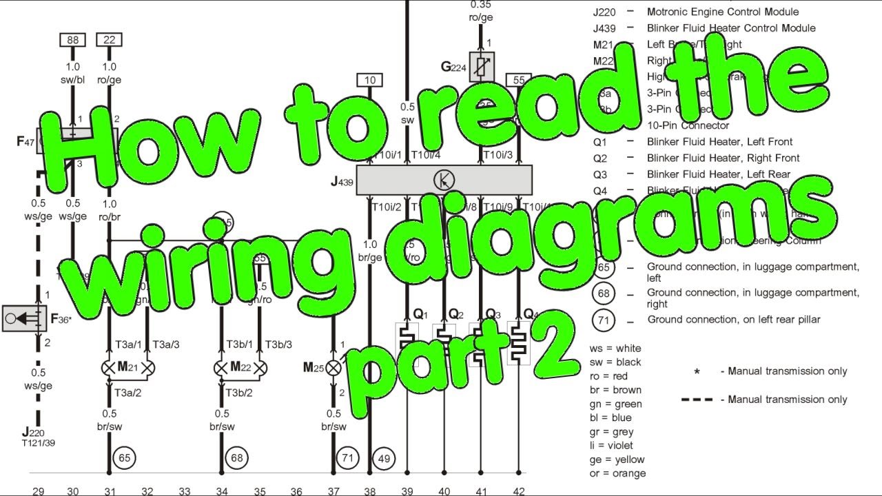
So, you're looking to dive deeper into your car's electrical system? That's fantastic! Automotive wiring diagrams can seem daunting at first, but with a little know-how, they can become your best friend for diagnosing problems, performing modifications, or even just understanding how your vehicle's systems work. Consider this your comprehensive guide. We’ll break down everything you need to know, from understanding the symbols to using a diagram for real-world troubleshooting. And the best part? We have the actual wiring diagram for your vehicle readily available for download.
Purpose: Why Understanding Wiring Diagrams Matters
Let's be honest, electrical gremlins are among the most frustrating automotive issues to deal with. A wiring diagram is more than just a schematic; it's your roadmap to navigating the complex network of wires, connectors, and components that make your car tick. Here’s why mastering the art of reading these diagrams is crucial:
- Accurate Diagnosis: Instead of blindly replacing parts, a wiring diagram allows you to trace circuits, identify faulty components, and pinpoint the exact location of a short, open, or high resistance connection.
- Safe and Effective Repairs: Working on electrical systems without understanding the wiring can be dangerous and lead to further damage. Diagrams provide the necessary information to disconnect components safely and ensure proper reconnection.
- Custom Modifications: Adding aftermarket accessories like lights, stereos, or alarms requires tapping into existing circuits. A wiring diagram is essential for identifying the correct wires and ensuring your modifications are done safely and reliably.
- In-Depth Learning: Even if you don't plan on performing repairs yourself, understanding wiring diagrams provides valuable insight into how your car's systems operate, allowing you to better understand and communicate with your mechanic.
Key Specs and Main Parts of a Wiring Diagram
Before we delve into the symbols, let's cover the fundamental elements you'll encounter in any automotive wiring diagram:
- Circuit Tracing: The core purpose of the diagram is to allow you to trace the flow of electricity through a specific circuit. Each circuit will typically originate at the power source (battery), pass through a switch or control module, power a load (like a light bulb or motor), and then return to ground.
- Components: Each component in the circuit is represented by a specific symbol. These can include batteries, fuses, relays, switches, sensors, actuators, and electronic control modules (ECMs).
- Wires: Wires are represented by lines, and their colors are often indicated using abbreviations (e.g., BLU for blue, RED for red, GRN for green). The gauge (thickness) of the wire may also be noted.
- Connectors: Connectors are represented by various symbols, often squares or circles. These symbols indicate where wires are joined together. Connector numbers are usually included for easy identification within the vehicle.
- Grounds: Grounds are represented by a symbol resembling an upside-down Christmas tree. They indicate where the circuit returns to the vehicle's chassis, providing a path for the current to flow back to the battery.
- Splices: These are points where multiple wires are joined together. They are often represented by a dot or a "T" intersection.
Decoding the Symbols: Lines, Colors, and Icons
This is where the magic happens! Understanding the symbols used in a wiring diagram is key to deciphering its information.
Lines and Colors
- Solid Lines: Represent a single wire.
- Dashed Lines: Often indicate a shielded wire or a CAN bus line (Controller Area Network – used for communication between electronic control units).
- Line Thickness: Can sometimes indicate the wire gauge (thicker line = thicker wire), but this isn't always consistent.
- Colors: Wire colors are almost always abbreviated. Here are some common ones:
- BLK: Black
- RED: Red
- BLU: Blue
- GRN: Green
- WHT: White
- YEL: Yellow
- BRN: Brown
- ORG: Orange
Common Component Icons
- Battery: Usually represented by a series of short and long lines.
- Fuse: A squiggly line inside a rectangle.
- Relay: A coil (representing the electromagnet) and a switch.
- Switch: A line that can be opened or closed to complete or break a circuit.
- Resistor: A zig-zag line.
- Capacitor: Two parallel lines.
- Diode: A triangle pointing to a line.
- Ground: The "upside-down Christmas tree" symbol.
- Light Bulb: A circle with a cross inside.
- Motor: A circle with an "M" inside.
- Sensors: Symbols vary depending on the type of sensor (e.g., temperature, pressure, position). Consult the diagram's legend for specific sensor symbols.
- Electronic Control Module (ECM): Usually represented by a rectangle with input and output lines.
Always refer to the diagram's legend or key. Different manufacturers may use slightly different symbols.
How It Works: Tracing a Circuit
Let's walk through a simplified example of tracing a headlight circuit. Imagine you’re looking at the diagram, and here's how you’d approach it:
- Start at the Source: Begin at the battery symbol. Trace the wire leading from the battery, which will likely go to a fuse (protection).
- Follow the Path: From the fuse, the wire might lead to a switch (headlight switch). When the switch is turned on, it completes the circuit.
- Power the Load: From the switch, the wire continues to the headlight bulb. The bulb lights up when it receives power.
- Return to Ground: From the bulb, a wire connects to a ground point on the vehicle's chassis. This completes the circuit, allowing current to flow back to the battery.
By following this process, you can trace the entire circuit and understand how each component interacts with the others.
Real-World Use: Basic Troubleshooting Tips
Now, let's put this knowledge into practice. Let's say your headlights aren't working. Here's how a wiring diagram can help:
- Consult the Diagram: Locate the headlight circuit diagram for your vehicle.
- Identify Potential Culprits: Based on the diagram, identify the key components in the circuit: fuse, switch, relay (if applicable), bulb, and wiring.
- Check the Obvious: Start with the easiest checks:
- Fuse: Check the fuse with a multimeter. Is it blown?
- Bulb: Is the bulb burned out?
- Voltage Testing: Use a multimeter to check for voltage at various points in the circuit:
- Is there voltage at the fuse?
- Is there voltage at the switch when it's turned on?
- Is there voltage at the headlight connector?
- Ground Check: Verify that the ground connection is solid. A poor ground can cause all sorts of electrical problems.
- Continuity Testing: If you suspect a broken wire, use a multimeter to check for continuity between two points on the wire.
By systematically checking each component and wire, you can narrow down the source of the problem and avoid unnecessary parts replacements.
Safety First: Identifying Risky Components
Working on automotive electrical systems can be dangerous if proper precautions aren't taken. Here are some components to be particularly cautious around:
- Battery: Always disconnect the negative battery terminal before working on any electrical system. This prevents accidental shorts and potential damage to your car's electronics.
- Airbag System: The airbag system is highly sensitive and can deploy unexpectedly if mishandled. Always disconnect the battery and wait at least 10 minutes before working on any component related to the airbag system. Consult the vehicle's service manual for specific safety procedures.
- High-Voltage Systems (Hybrids/EVs): Hybrid and electric vehicles contain high-voltage systems that can be lethal. Never attempt to work on these systems unless you are properly trained and equipped.
- Capacitors: Capacitors can store a charge even after the power is disconnected. Discharge capacitors before handling them.
Always consult your vehicle's service manual for specific safety precautions and procedures.
Final Thoughts: Your Wiring Diagram Awaits
Reading automotive wiring diagrams is a skill that improves with practice. Don't be afraid to dive in, experiment, and learn from your mistakes. Start with simple circuits and gradually work your way up to more complex ones. And remember, we have the wiring diagram file for your vehicle ready for you to download. This will be your most valuable tool in mastering your car's electrical system.
Good luck, and happy troubleshooting!