
How To Read Automotive Wiring Schematics
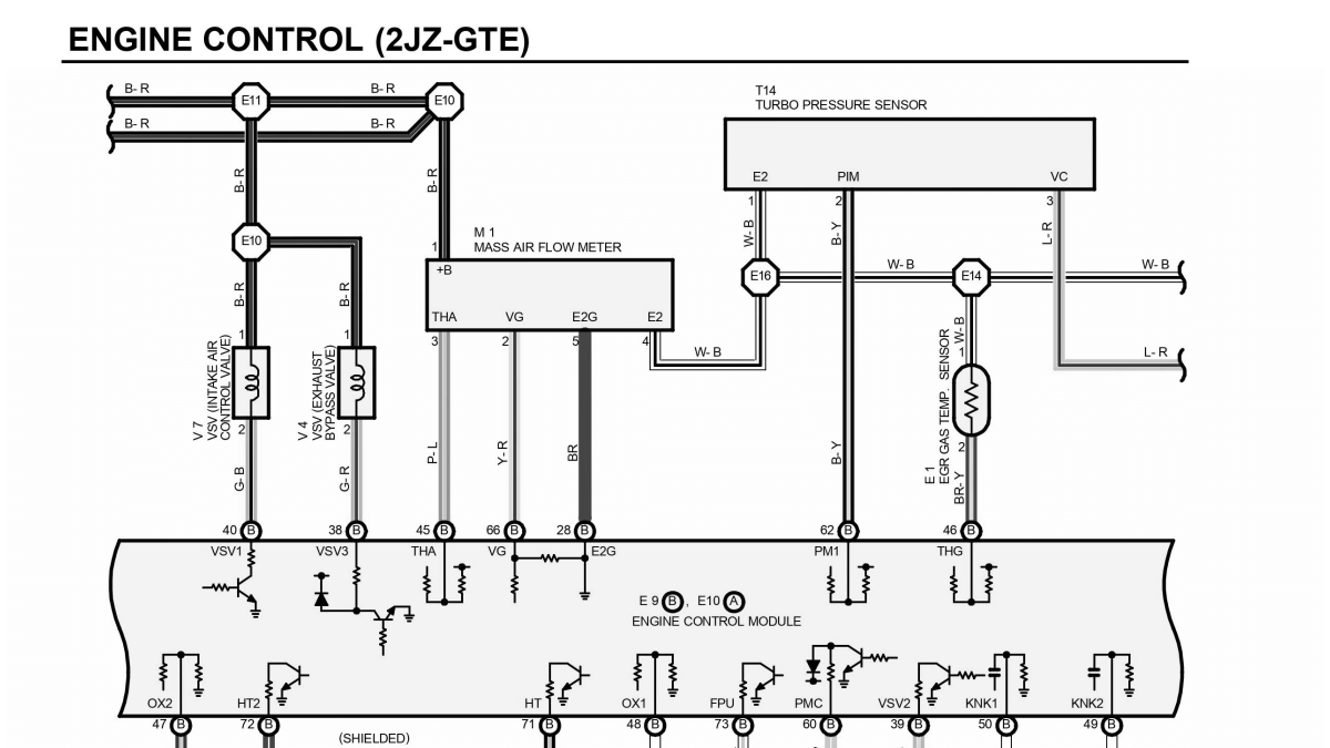
Welcome, fellow gearheads and DIY enthusiasts! Let’s dive into the fascinating world of automotive wiring schematics. Whether you're chasing down a phantom electrical issue, planning a custom modification, or simply trying to better understand your vehicle, mastering these diagrams is an invaluable skill. Think of them as a roadmap to your car's electrical system, and with a little practice, you'll be navigating them like a pro.
Why Bother with Schematics?
Why spend the time learning to read these diagrams? The answer is simple: control and understanding. Instead of throwing parts at a problem and hoping something sticks, a schematic allows you to trace circuits, identify components, and pinpoint the exact location of a fault. This saves you time, money, and a whole lot of frustration. Here’s a few practical applications:
- Troubleshooting: Is your turn signal blinking too fast? A schematic will help you isolate the issue to a specific bulb, wiring section, or relay.
- Modifications: Planning to install aftermarket lights, a new sound system, or a performance chip? Understanding the existing wiring is crucial for a safe and seamless integration.
- Repair Work: Fixing damaged wiring harnesses, replacing faulty sensors, or even rebuilding parts of your engine management system becomes much easier with a clear schematic.
- Vehicle Information: If you want to deeply understand how certain functions are implemented in your car, reading the car's schematic diagram will provide important details.
Ultimately, schematics empower you to take ownership of your vehicle's electrical system. You're no longer reliant on guesswork; you're working with knowledge.
Key Specs and Main Parts of a Wiring Diagram
Before we get into the nitty-gritty, let's familiarize ourselves with the basic layout and key components of a typical automotive wiring schematic. The goal is to get a good grasp of what to expect.
- Power Source: Usually, this is the battery, represented by a symbol resembling a series of plates. It is marked with positive (+) and negative (-) terminals. From the battery, the diagram shows how power distributes to various circuits through fuses, relays and switches.
- Ground: Often indicated by a symbol resembling stacked triangles or a similar grounding symbol. It represents the return path for current to the negative terminal of the battery. All the grounded connections should have continuity, allowing current to complete a circuit.
- Wires: Solid lines represent wires, each with a specific color code and gauge. Wire gauge is a measurement of its thickness, and the color code denotes the wire's function (e.g., red for power, black for ground).
- Connectors: These are points where wires connect or split. They're usually depicted as circles, squares, or other simple geometric shapes.
- Fuses: Safety devices designed to protect circuits from overcurrent. They're typically drawn as a zigzag line inside a rectangle. The schematic typically includes the fuse rating (in amperes) and its location.
- Relays: Electrically operated switches that control circuits with high current draw using a low-current signal. Relays are usually shown as a coil and a set of contacts.
- Switches: Control the flow of electricity in a circuit. They are drawn based on their type (e.g., toggle, rotary, momentary).
- Components: These are the actual electrical devices, such as lights, sensors, actuators, and modules (like the ECU – Engine Control Unit). Each component has its unique symbol and a descriptive label, sometimes along with a part number.
- Splices: Points where multiple wires are joined together. They're often represented by a dot or a small circle.
Deciphering the Symbols: Lines, Colors, and Icons
Understanding the symbols is paramount to reading any schematic. Let's break down the common ones:
Lines
- Solid Lines: Represent conductive wires carrying electrical current.
- Dotted/Dashed Lines: May represent shielded wiring, data communication lines (like CAN bus), or optional wiring depending on the vehicle configuration.
- Thick Lines: Often indicate wires that carry a higher current.
Colors
Each wire is designated with a color code, often a combination of two or three letters. Here are some common ones:
- BK: Black (usually ground)
- RD: Red (usually power)
- WH: White
- BL: Blue
- GN: Green
- YW: Yellow
- OR: Orange
- BR: Brown
- VT: Violet
- GY: Gray
Example: A wire labeled "RD/BK" is a red wire with a black stripe.
Icons
Component symbols can vary, but here are some typical representations:
- Resistor: Zigzag line.
- Capacitor: Two parallel lines.
- Inductor/Coil: Series of curved lines resembling a coil.
- Diode: Triangle pointing to a vertical line.
- Transistor: Three lines connected in a specific configuration.
- Ground: Three lines getting smaller, that are stacked on each other.
Consult the specific schematic's legend or key to confirm the exact symbols used.
How It Works: Tracing the Circuit
Now for the fun part: following the flow of electricity through the schematic. Imagine electricity as water flowing through pipes. You're tracing the path from the power source (the battery) to the component and back to ground.
- Start at the Power Source: Identify the battery symbol and trace the wire leading from the positive (+) terminal.
- Follow the Wires: Pay attention to color codes and wire gauge. Note any fuses or relays along the path.
- Pass Through Components: Observe how the electricity flows through switches, sensors, or other devices.
- Reach the Ground: Trace the wire from the component back to the negative (-) terminal of the battery via a grounding point.
Example: Let's say you're tracing the circuit for a headlight. You'd start at the battery, follow the wire through a fuse, then through a headlight switch, and finally to the headlight itself. From the headlight, you'd follow another wire to a ground point on the chassis.
Real-World Use: Basic Troubleshooting Tips
Here are some basic troubleshooting tips using a schematic:
- No Power to a Component: Use the schematic to trace the power supply path. Check the fuse first. Then, use a multimeter to check for voltage at each connection point along the wire.
- Component Not Functioning: Verify that the component is receiving power and has a good ground connection. Test the component itself to rule out a fault within the device.
- Short Circuit: Look for areas where wires might be damaged or pinched, causing them to come into contact with the vehicle's chassis (ground). The schematic can help you identify potential trouble spots.
- Excessive Current Draw: Use a multimeter to measure the current flowing through a circuit. Compare this value to the schematic's specifications. High current draw can indicate a short circuit or a faulty component.
Important: Always disconnect the battery's negative terminal before working on the electrical system to prevent accidental shorts or shocks.
Safety Considerations
Working with automotive electrical systems can be dangerous. Here are some critical safety precautions:
- Disconnect the Battery: Always disconnect the negative terminal of the battery before working on any electrical component.
- High-Voltage Components: Be extremely careful when working with components that handle high voltage, such as the ignition system or hybrid/electric vehicle systems. These systems can deliver a lethal shock. If you are unsure, consult a qualified technician.
- Airbag Systems: Airbag systems are sensitive and can deploy unexpectedly if handled incorrectly. Refer to the vehicle's service manual for specific instructions on disabling the airbag system before working near it.
- Use Proper Tools: Use insulated tools designed for automotive electrical work. This includes multimeters, wire strippers, crimpers, and test lights.
- Double-Check Your Work: Before reconnecting the battery, double-check all connections to ensure they are secure and properly insulated.
We have the wiring schematic file to help you get started. This specific diagram covers [Insert specific car Model/Year/System] and includes detailed information on [Mention specific systems covered - e.g., engine management, lighting, etc.]. You can download it here: [Provide Download Link or instructions].
With practice and patience, you'll be able to confidently read and use automotive wiring schematics to diagnose and repair your vehicle's electrical system. Happy wrenching!