How To Read Car Electrical Wiring Diagrams
So, you're ready to tackle some electrical work on your car? Excellent! Understanding car electrical wiring diagrams is absolutely crucial. Think of them as the Rosetta Stone for automotive electrics. Without them, you're navigating a complex network blindfolded. With them, you can diagnose problems, install aftermarket accessories, and perform modifications with confidence. This guide will provide you with the foundational knowledge you need to read and interpret these diagrams effectively.
Purpose: Why Bother Learning This?
Why spend the time learning to decipher these diagrams? Simply put, they're invaluable for a multitude of reasons. Firstly, they are essential for diagnosing electrical faults. A wiring diagram allows you to trace a circuit from power source to component, pinpointing breaks, shorts, or faulty relays. Secondly, they make installing aftermarket accessories – like stereos, alarms, or auxiliary lighting – far easier and safer. Thirdly, if you are modifying your car, such as doing an engine swap or altering the wiring for performance enhancements, you must understand the wiring diagrams to avoid catastrophic electrical issues. Finally, even if you're just curious about how your car's electrical system works, understanding these diagrams provides a deep and fascinating insight into its inner workings.
Key Specs and Main Parts of an Electrical Diagram
Before diving into the symbols, it's important to understand the basic layout and key components represented in a wiring diagram. Here are some of the common elements you'll encounter:
- Power Source: This is usually the battery, represented by a symbol that looks like a series of alternating long and short lines. The diagram will indicate the positive (+) and negative (-) terminals.
- Fuses and Circuit Breakers: These are safety devices designed to protect the circuit from overloads. They're typically shown as a small rectangle with a squiggly line inside. The amperage rating (e.g., 10A, 20A) will often be indicated next to the symbol.
- Relays: These are electrically operated switches that allow a low-current circuit to control a high-current circuit. They're usually represented by a coil and a switch symbol.
- Switches: These control the flow of electricity in a circuit (e.g., headlight switch, ignition switch). Different types of switches (SPST, SPDT, DPDT, etc.) have different symbols.
- Loads: These are the components that use electricity (e.g., headlights, motors, sensors). Each type of load has its own specific symbol.
- Wiring Harnesses: These are bundles of wires that are grouped together and often protected by a sheath. The diagram will show how the wires are routed and connected within the harness.
- Connectors: These are used to join different parts of the wiring harness or to connect components. They're often represented by a series of interlocking shapes. The diagram usually indicates the connector number or identification.
- Grounds: Represented by a symbol resembling a tree or an inverted pyramid, grounds are points where the circuit connects to the car's chassis, providing a return path for the current. A good ground is essential for proper circuit operation.
Understanding Symbols: The Language of Electrics
The heart of reading wiring diagrams lies in understanding the symbols used. While there can be slight variations between manufacturers, some symbols are almost universally recognized. Let's break down the key elements:
Lines: The Pathways of Electricity
- Solid Lines: Represent wires. The thicker the line, the thicker the wire *generally* is, and hence the higher its current carrying capacity.
- Dotted Lines: Can represent shielded wires, or sometimes indicate wires that are part of a shared harness but are not directly related to the circuit being shown. Also used to indicate optional or future connections.
- Arrows: Indicate the direction of current flow (though, technically, electrons flow from negative to positive, diagrams usually show conventional current flow from positive to negative).
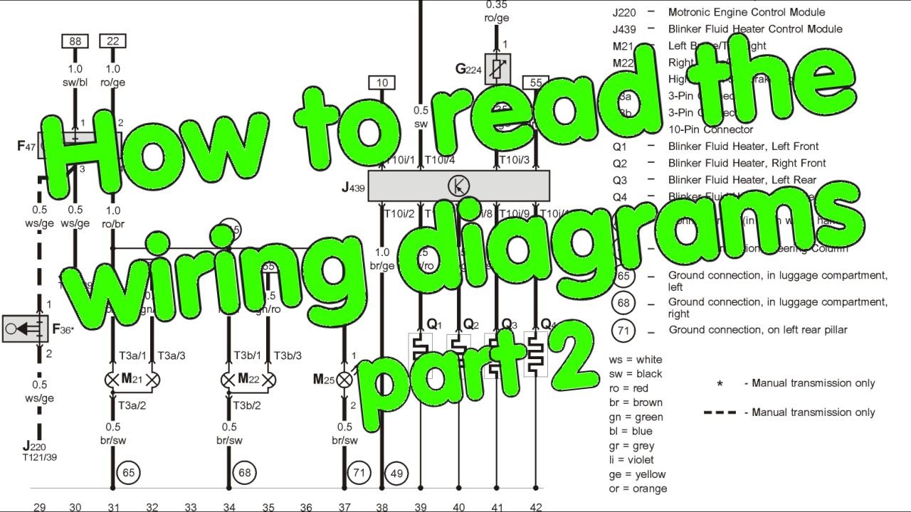
Colors: Identifying Wires
Wire colors are critically important. Wiring diagrams will use abbreviations for colors, such as:
- BK = Black
- RD = Red
- BL = Blue
- GN = Green
- YE = Yellow
- WT = White
- OR = Orange
- BR = Brown
- VT = Violet
Often, a wire will have a primary color and a stripe color. For example, "RD/BK" would indicate a red wire with a black stripe. This helps differentiate wires within a harness.
Icons: Representing Components
As mentioned earlier, each component has a specific symbol. Familiarize yourself with common symbols for fuses, relays, switches, lights, motors, and sensors. A legend or key is usually provided on the diagram itself to explain the symbols used.
Pro Tip: Pay close attention to the legend provided with the wiring diagram. It's the key to unlocking the diagram's secrets.
How It Works: Tracing a Circuit
The core skill in using a wiring diagram is tracing a circuit. Here's a simplified example. Let's say you're troubleshooting why your headlights aren't working.
- Start at the Power Source: Locate the battery symbol on the diagram.
- Follow the Path: Trace the wire from the battery's positive terminal to the headlight switch. Note any fuses or relays in the circuit.
- Check the Switch: Verify that the switch is functioning correctly (i.e., it's closing the circuit when turned on).
- Continue to the Load: Trace the wire from the switch to the headlights.
- Check the Ground: Ensure that the headlights have a good ground connection.
By systematically tracing the circuit, you can identify the point where the electrical flow is interrupted.
Real-World Use: Basic Troubleshooting Tips
Here are some practical tips for using wiring diagrams in real-world troubleshooting scenarios:
- Use a Multimeter: A multimeter is your best friend. Use it to check for voltage, continuity, and resistance in the circuit.
- Check Fuses First: Blown fuses are the most common cause of electrical problems.
- Inspect Connectors: Look for corroded or loose connectors. Clean and re-secure them as needed.
- Test Relays: Relays can fail intermittently. You can often test them by swapping them with a known good relay.
- Isolate the Problem: If you're dealing with a complex circuit, try to isolate the problem by disconnecting sections of the circuit and testing them individually.
Safety: Proceed with Caution!
Working with automotive electrics can be dangerous. Here are some safety precautions to keep in mind:
- Disconnect the Battery: Before working on any electrical circuit, disconnect the negative terminal of the battery.
- Avoid Shorts: Be careful not to short circuit any wires. This can damage components or cause a fire.
- Work in a Well-Ventilated Area: Battery acid and other chemicals can be harmful.
- Be Aware of High-Voltage Components: Especially in hybrid or electric vehicles, be extremely cautious around high-voltage components. These systems can deliver a lethal shock. It is generally not recommended to DIY repair high voltage circuits.
- Consult a Professional: If you're not comfortable working on a particular circuit, or if you're dealing with a complex electrical problem, consult a qualified automotive electrician.
We have a sample wiring diagram file available for download. It will help you practice the skills you learned in this article. It includes detail of components, wires, and related information. You can download it HERE.