
How To Read Electrical Wiring Diagram
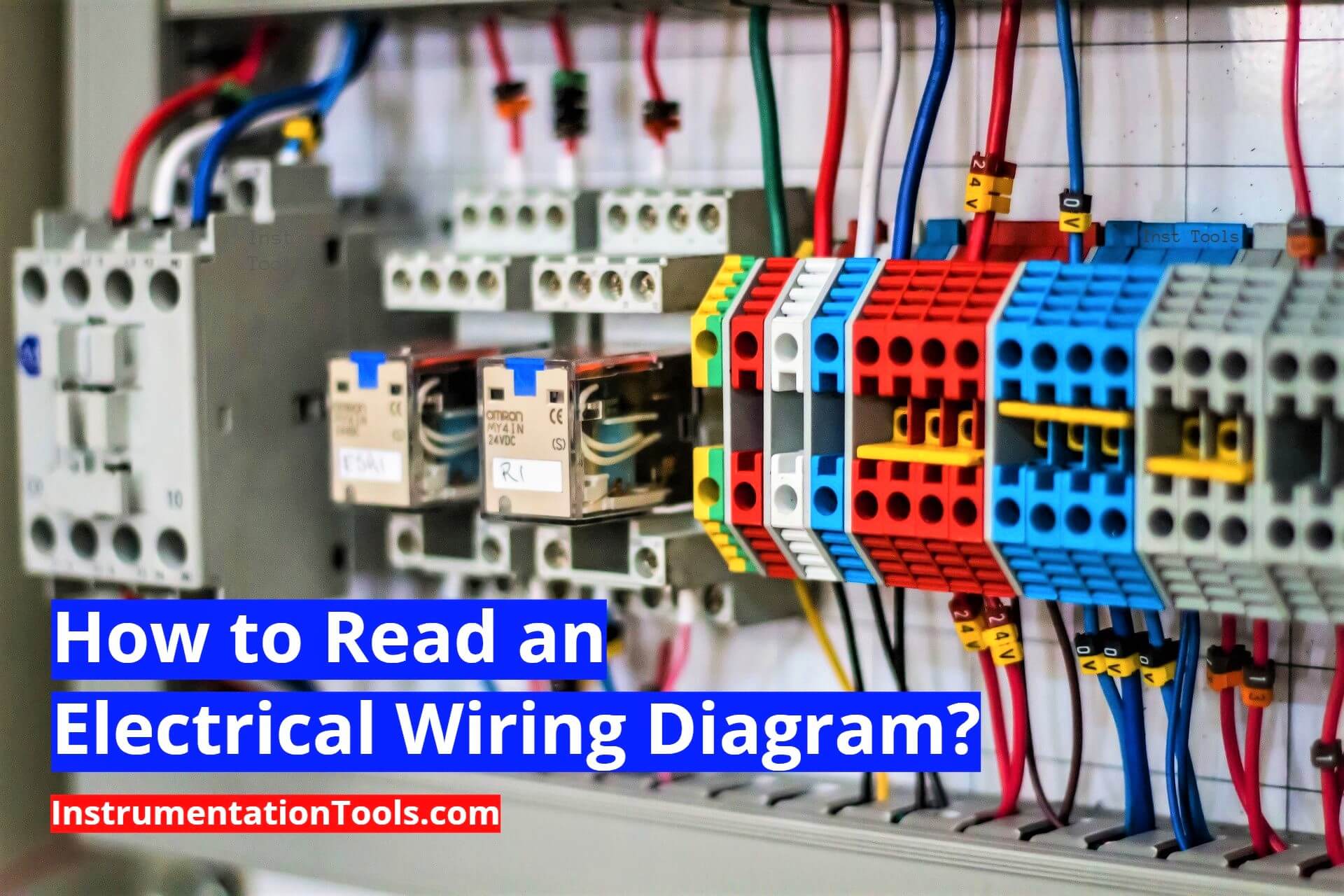
Alright, let's dive into the world of electrical wiring diagrams! For those of us who like to get our hands dirty fixing or modifying our cars, these diagrams are absolutely essential. Think of them as the roadmap to your car's electrical system. Without them, you're basically poking around in the dark hoping for the best, which is never a good idea, especially when dealing with electricity.
Purpose: Your Electrical Roadmap
Why bother learning to read these things? Well, the benefits are huge. Primarily, wiring diagrams are crucial for troubleshooting electrical problems. Is your turn signal not working? Do you suspect a short circuit draining your battery? A wiring diagram will guide you to the components involved, the wiring connecting them, and potential points of failure. But it's not just for fixing things. They are also invaluable for:
Modifications: Adding aftermarket lights, sound systems, or performance upgrades becomes much safer and more reliable when you can confidently tap into the existing electrical system. Knowing where to find the correct power source and how to safely ground your new device is essential.
Understanding your car: Beyond repairs and mods, understanding the wiring diagram provides a deeper understanding of how your vehicle's systems function. You can trace the flow of electricity from the battery to various components and learn about the logic behind the design.
Preventative Maintenance: Wiring diagrams can assist in identifying potential problem areas before they manifest into major issues. For example, you can use the diagram to inspect critical connections and wiring harnesses for corrosion or damage.
Key Specs and Main Parts of a Wiring Diagram
Before we jump into the specifics, let's understand the basic components you'll typically find in a wiring diagram:
- Power Source: Usually the battery, represented by a symbol showing positive (+) and negative (-) terminals.
- Ground: The return path for electricity, typically connected to the car's chassis. Often indicated by the ground symbol (three horizontal lines decreasing in size). Proper grounding is crucial for the operation of all electrical components.
- Wiring: Lines connecting components, often color-coded to differentiate circuits.
- Fuses/Circuit Breakers: Protection devices that interrupt the circuit if the current exceeds a safe level. Represented by various symbols (e.g., a zigzag line or a rectangle with a line through it). They are designed to protect the wiring and components from damage caused by overcurrent conditions.
- Switches: Devices that open or close a circuit. Represented by symbols showing the switch contacts in their open or closed positions.
- Relays: Electrically operated switches, used to control high-current circuits with a low-current signal. Consist of a coil and a set of contacts.
- Components: Bulbs, motors, sensors, actuators – anything that uses electricity. Represented by various symbols specific to the type of component.
- Connectors: Points where wires are joined together. Essential for modularity and ease of repair.
- Splices: Points where multiple wires are joined together electrically, but not through a connector.
- ECU (Engine Control Unit)/Modules: The brains of the system, controlling various functions based on sensor inputs and programmed logic. Often represented by a rectangle with input and output connections.
Decoding the Symbols: Lines, Colors, and Icons
This is where things get interesting. Let's break down the common elements you'll encounter:
Lines
Lines represent wires. A solid line indicates a direct connection. A dashed or dotted line might indicate a shielded wire, a data bus line (like CAN bus), or a ground connection.
Colors
Wire colors are extremely important. They allow you to trace a specific wire throughout the system. Wiring diagrams typically use abbreviations for colors, such as:
- BK: Black
- RD: Red
- BL: Blue
- GN: Green
- WH: White
- YL: Yellow
- OR: Orange
- BR: Brown
Sometimes, you'll see two colors separated by a slash (e.g., "GN/WH"). This means the wire is green with a white stripe. Make sure you have a color code key for your specific vehicle, as some manufacturers use different abbreviations.
Icons
Icons represent the actual components. Here are some common ones:
- Resistor: Zigzag line.
- Capacitor: Two parallel lines.
- Diode: Triangle pointing to a line.
- Transistor: Circle with three lines emanating from it.
- Coil/Inductor: Series of loops.
- Ground: Three horizontal lines decreasing in size, or a symbol resembling an upside-down Christmas tree.
- Fuse: A small rectangle with a wire through it.
- Battery: Series of short and long parallel lines representing the cells.
Keep in mind that icons can vary slightly between manufacturers and diagrams. Always refer to the diagram's legend for specific definitions.
How It Works: Tracing the Circuit
The key to understanding a wiring diagram is tracing the flow of electricity. Start at the power source (battery). Follow the wire (line) to the first component (e.g., a switch). When the switch is closed, electricity flows through it to the next component (e.g., a fuse). The electricity continues to flow through the circuit until it reaches the load (e.g., a light bulb) and then returns to ground, completing the circuit.
Consider a simple headlight circuit: Power flows from the battery through a fuse, then to the headlight switch. When you turn the switch on, power is sent to the headlight bulb. The other side of the bulb is connected to ground. If any part of this circuit is broken (e.g., a blown fuse, a broken wire, a faulty switch, or a burned-out bulb), the headlight will not work.
Real-World Use: Basic Troubleshooting Tips
Okay, you've got the basics down. Let's put this knowledge to use with some basic troubleshooting:
- Identify the Symptom: What's not working? Be specific (e.g., "Left turn signal doesn't work").
- Locate the Relevant Circuit: Find the wiring diagram for the affected system. Your vehicle's repair manual is a must-have for this.
- Trace the Circuit: Starting from the power source, follow the circuit to the affected component. Look for common points of failure like fuses, switches, relays, and connectors.
- Test Components: Use a multimeter to check for voltage and continuity. For example, check if power is reaching the bulb. Check the fuse for continuity (it should read close to 0 ohms if it's good). Check the switch for proper operation.
- Isolate the Problem: By systematically testing components, you can narrow down the source of the issue.
Example: If your tail lights aren't working, consult the wiring diagram. Check the tail light fuse first. If the fuse is blown, replace it. If it blows again immediately, you likely have a short circuit. The wiring diagram will help you identify potential areas where the wires might be shorting to ground.
Safety: Handle with Care
Working with electrical systems can be dangerous. Always remember:
- Disconnect the Battery: Before working on any electrical component, disconnect the negative terminal of the battery. This will prevent accidental shorts and potential shocks.
- Use the Right Tools: Use insulated tools specifically designed for electrical work.
- Be Careful with High-Voltage Components: Components like the ignition system and certain sensors can carry high voltage even after the car is turned off. Refer to your repair manual for specific safety precautions.
- Don't Cut Wires Blindly: Always identify the wire using the wiring diagram before cutting it.
- Double-Check Your Work: Before reconnecting the battery, double-check all your connections to ensure they are secure and properly insulated.
High-risk components often include the SRS (Airbag) system and the ABS (Anti-lock Braking System). Incorrectly handling these systems can lead to serious injury. If you are not comfortable working with these systems, it is best to seek the help of a qualified technician.
Understanding electrical wiring diagrams takes practice, but it's a skill that will pay off handsomely in the long run. Start with simple circuits and gradually work your way up to more complex systems. Remember to always prioritize safety and consult your vehicle's repair manual for specific instructions and warnings. And don't be afraid to ask for help from experienced mechanics or online forums.
We have a sample electrical wiring diagram file for your practice. You can download it here.