How To Read Wiring Diagrams For Cars
Alright, so you're ready to tackle the mysteries hidden within your car's wiring. Understanding wiring diagrams isn't just about fixing that blown fuse; it's about truly understanding how your vehicle's electrical system functions. This knowledge empowers you to diagnose problems accurately, perform modifications safely, and even customize your car's electronics with confidence. We have a sample wiring diagram file that you can download to follow along. Think of it as your roadmap to electrical mastery.
Purpose: Why Bother Learning Wiring Diagrams?
Why should you, a capable DIYer, bother learning how to read wiring diagrams? Several compelling reasons exist:
- Accurate Diagnostics: No more guessing games! Wiring diagrams pinpoint exactly where circuits run, helping you isolate faulty components quickly. Imagine trying to find a short without knowing where the wire even goes – a diagram saves immense time and frustration.
- Safe Repairs: Working with electricity is inherently dangerous. A wiring diagram provides a clear understanding of the system, reducing the risk of accidental shorts, fires, or worse – personal injury.
- Confident Modifications: Adding aftermarket accessories (lights, stereos, alarms) becomes significantly easier when you understand the existing wiring. You can integrate new components seamlessly and safely.
- Enhanced Learning: Understanding wiring diagrams deepens your overall automotive knowledge. You'll develop a far better understanding of how various systems interact and function.
Key Specifications and Main Parts of a Wiring Diagram
Before we dive into the specifics, let's familiarize ourselves with the core elements of a typical automotive wiring diagram. These elements are the building blocks for understanding the overall circuit.
- Power Source: Typically the battery (12V in most cars), indicated by a symbol resembling a battery or labeled with "BATT" or "+12V".
- Ground (Earth): The return path for the current, usually the car's chassis. Represented by various ground symbols, often resembling stacked triangles or a downward-pointing arrow.
- Wires: Conductors that carry the electrical current. Shown as lines connecting components. Their color is usually indicated in the diagram, a critical piece of information.
- Fuses and Circuit Breakers: Safety devices that protect circuits from overcurrents. Fuses are indicated by a rectangular box with a wavy line inside; circuit breakers have similar symbols.
- Switches: Devices that open or close circuits, controlling the flow of current. Represented by various symbols, depending on the type of switch (e.g., single-pole single-throw - SPST, single-pole double-throw - SPDT).
- Relays: Electrically operated switches that control high-current circuits using a low-current signal. Indicated by a coil and a switch symbol.
- Connectors: Points where wires are joined together. Shown as circles or other symbols, often with pin numbers for identification.
- Components: The actual electrical devices in the circuit (e.g., lights, motors, sensors, actuators). Represented by specific symbols for each type of component.
- Control Modules (ECUs): Electronic Control Units are mini-computers that control various functions. Typically represented as a rectangular block with labeled inputs and outputs.
Understanding Symbols: Lines, Colors, and Icons
Deciphering the symbols is crucial. Here's a breakdown of the most common ones:
Lines: The Electrical Highways
- Solid Lines: Represent wires carrying electrical current. The thickness of the line sometimes indicates the wire gauge (thicker lines = larger gauge = can handle more current).
- Dashed Lines: Can indicate a shielded wire, a ground connection, or a wire that exists on a separate page of the diagram. Consult the diagram's legend.
- Lines Crossing: If lines cross without a dot at the intersection, it usually means they are not connected. A dot indicates a connection.
Colors: Following the Rainbow (Electronically)
Wire colors are vital for tracing circuits. Common abbreviations are:
- BK: Black (usually ground)
- RD: Red (often power)
- BL: Blue
- GN: Green
- WH: White
- YL: Yellow
- OR: Orange
- BR: Brown
- VT: Violet (Purple)
- GY: Gray
Often, wires are striped with a second color. For example, "WH/BK" means a white wire with a black stripe. These color codes are usually indicated next to the wire line in the diagram. Always double-check the color against the physical wire in the car.
Icons: Picturing the Components
Component symbols can vary between manufacturers and even model years, but here are some common ones:
- Resistors: Zigzag line.
- Capacitors: Two parallel lines.
- Diodes: Triangle pointing towards a vertical line.
- Lights (Bulbs): Circle with an "X" inside.
- Motors: Circle with "M" inside.
- Solenoids: Coil symbol (similar to a relay coil).
- Sensors: Symbols vary greatly depending on the type of sensor (e.g., temperature sensor, pressure sensor). Consult the diagram's legend.
How It Works: Tracing a Circuit
The key to reading a wiring diagram is to trace the flow of electricity. Start at the power source (battery) and follow the wire through the circuit, noting each component it passes through. This is where understanding the symbols and color codes comes into play.
- Identify the Power Source: Find the battery symbol and trace the wire coming from the positive (+) terminal.
- Follow the Wire: Note the wire color and any splices or connectors along the way.
- Identify Components: Recognize the symbols for fuses, switches, relays, and the final load (e.g., light bulb, motor).
- Track the Ground Path: After passing through the load, the circuit must return to the negative (-) terminal of the battery through a ground connection.
Many diagrams use reference numbers or zone identifiers to help you locate components and wiring on different pages. Make sure you understand how these references work to effectively navigate the diagram.
Real-World Use: Basic Troubleshooting Tips
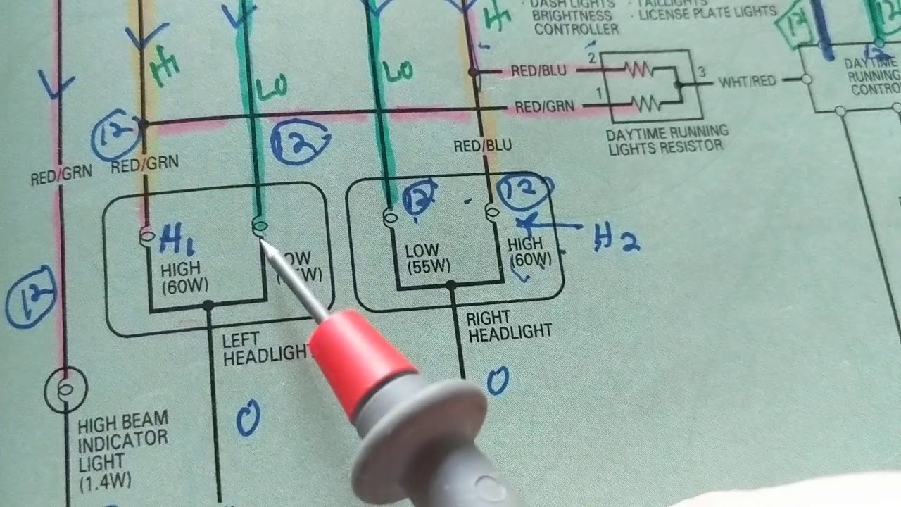
Let's say your headlights aren't working. Here's how a wiring diagram can help:
- Consult the Diagram: Find the headlight circuit in the wiring diagram.
- Check the Fuse: Locate the fuse for the headlights and visually inspect it. If it's blown, replace it with the correct amperage fuse.
- Test the Switch: Use a multimeter to check if the headlight switch is sending power to the circuit when turned on.
- Trace the Wiring: If the switch is good, follow the wiring from the switch to the headlights, checking for broken wires, loose connections, or corrosion.
- Check the Ground: Verify that the headlights have a good ground connection.
A multimeter is your best friend when troubleshooting electrical issues. Use it to check for voltage, continuity (a complete path for current), and resistance.
Also remember to check Technical Service Bulletins (TSBs) for your vehicle make and model, as these frequently cover known wiring harness or connection issues.
Safety: Respect the Electricity
Working with automotive electrical systems can be dangerous. Here are some crucial safety precautions:
- Disconnect the Battery: Always disconnect the negative (-) battery terminal before working on any electrical components. This prevents accidental shorts and shocks.
- Use Proper Tools: Use insulated tools designed for automotive electrical work.
- Never Bypass Fuses: Fuses protect circuits from overcurrents. Never replace a blown fuse with a higher amperage fuse or bypass it altogether. This can lead to a fire.
- Be Careful Around Airbags: Airbag systems are extremely sensitive and can deploy unexpectedly if mishandled. Consult the service manual for proper procedures before working near airbags.
- High-Voltage Components: Hybrid and electric vehicles contain high-voltage components that can be lethal. Do not attempt to work on these systems unless you are properly trained and equipped.
Always refer to the vehicle's service manual for specific safety instructions and procedures. If you're unsure about anything, consult a qualified mechanic.
With practice and patience, you'll be able to confidently read and interpret automotive wiring diagrams. Remember to take your time, double-check your work, and prioritize safety. You can download the sample wiring diagram file to start practicing right away. Happy wiring!