
Hvac Blower Motor Relay Wiring Diagram
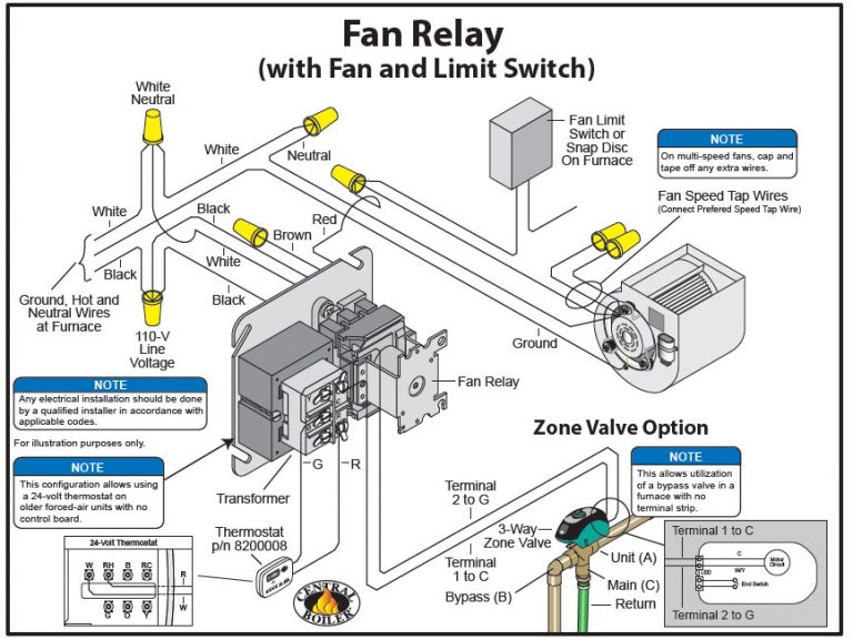
Alright, let's dive into the intricate world of HVAC blower motor relay wiring diagrams. Whether you're wrestling with a stubborn blower motor, trying to diagnose a climate control issue, or just expanding your automotive know-how, understanding this diagram is crucial. We're going to approach this like two seasoned mechanics discussing a complex problem, so expect some technical jargon, but I'll break it down as we go.
Purpose of the Blower Motor Relay Wiring Diagram
Why bother with this seemingly cryptic schematic? Well, it's your roadmap to understanding how the blower motor, the component responsible for circulating air in your car's HVAC system, receives power. A diagram is essential for:
- Diagnosis: Pinpointing the source of a blower motor failure (e.g., a bad relay, wiring fault, or a faulty motor itself).
- Repair: Replacing damaged wiring or components with confidence.
- Modification: Adding aftermarket climate control features or upgrading your existing system.
- Understanding: Simply grasping the fundamentals of your car's electrical system.
Without a proper diagram, you're essentially poking around in the dark, risking further damage and frustration. Think of it as the blueprint for the electrical circuit that powers your comfort.
Key Specs and Main Parts
Before we decipher the diagram, let's identify the major players:
- Battery: The source of DC power for the entire system. Typically 12V in automotive applications.
- Ignition Switch: Controls the flow of power to various circuits when the car is running.
- Fuse: A safety device that protects the circuit from overcurrent. It melts and breaks the circuit if the current exceeds a predetermined limit.
- Blower Motor Resistor (or Blower Motor Control Module): This component controls the speed of the blower motor. Older vehicles use resistors, while newer ones often employ a more sophisticated control module, using PWM (Pulse Width Modulation) to regulate voltage.
- Blower Motor Relay: An electromagnetic switch that allows a small current (from the control panel) to control a much larger current (to the blower motor). This prevents excessive current draw on the control panel and related wiring.
- Blower Motor: The electric motor that spins the fan, which moves air through the HVAC system.
- Ground (Chassis Ground): Provides a return path for the electrical current back to the battery.
- HVAC Control Panel: The user interface where you select fan speed, temperature, and air direction.
These components interact in a specific sequence, all orchestrated by the wiring diagram. Understanding their functions is the first step to understanding the diagram itself.
Decoding the Symbols: Lines, Colors, and Icons
Wiring diagrams use standardized symbols to represent electrical components and connections. Here's a quick rundown:
- Solid Lines: Represent wires. The thicker the line, generally the higher the current carrying capacity of the wire.
- Dashed Lines: Often indicate control signals or communication lines.
- Colors: Wires are color-coded for easy identification. Common colors include red (power), black (ground), blue, yellow, green, and white. The specific color code will vary depending on the vehicle manufacturer. Always consult the vehicle-specific wiring diagram to understand the color codes.
- Circles: Can represent connectors or splices in the wiring.
- Rectangles: Typically represent components like relays, resistors, or control modules.
- Zig-zag Lines: Represent resistors.
- Coils: Represent relay coils or inductor coils (sometimes present in control modules).
- Ground Symbol: Looks like a series of descending lines connected to a point, indicating a connection to the vehicle's chassis ground.
Pay close attention to the annotations on the diagram. These labels identify the component, wire gauge (e.g., 16 AWG), and circuit number. They are crucial for accurate diagnosis and repair.
How It Works: The Relay in Action
Let's trace the flow of electricity through a typical blower motor relay circuit:
- The ignition switch is turned to the "on" position, providing power to the HVAC control panel.
- You select a fan speed on the control panel. This sends a signal (a small current) to the blower motor relay coil.
- When the relay coil is energized, it creates a magnetic field. This magnetic field pulls the relay's internal switch closed.
- Closing the relay switch completes a separate, high-current circuit. This circuit runs directly from the battery (via a fuse) to the blower motor.
- The blower motor receives power and begins to spin, circulating air. The blower motor resistor (or control module) regulates the voltage supplied to the motor, controlling its speed.
- The circuit is completed back to the battery through the vehicle's chassis ground.
The relay acts as an intermediary, allowing a low-current signal from the control panel to switch a high-current circuit to the blower motor. This protects the control panel from damage and simplifies the wiring.
Real-World Use: Basic Troubleshooting
Here's how you can use the wiring diagram to troubleshoot common blower motor problems:
- Blower motor doesn't work at all:
- Check the blower motor fuse. Is it blown? Replace it with a fuse of the same amperage.
- Check the blower motor relay. You can often swap it with an identical relay from another circuit (e.g., the horn relay) to see if that fixes the problem. If so, replace the faulty relay.
- Use a multimeter to check for voltage at the blower motor connector. If there's no voltage, trace the circuit back towards the battery, checking for breaks in the wiring or faulty connections.
- Blower motor only works on some speeds:
- This is often a sign of a faulty blower motor resistor (or control module). Use a multimeter to test the resistor's continuity. If any of the resistors are open (no continuity), replace the resistor pack. For control modules, consult the vehicle-specific service manual for testing procedures.
- Blower motor runs constantly, even with the ignition off:
- This could indicate a short in the wiring or a stuck blower motor relay. Disconnect the relay to see if the motor stops. If it does, replace the relay.
Always refer to the specific wiring diagram for your vehicle. Generic diagrams can provide a general understanding, but the actual wiring and component locations can vary significantly.
Safety First: Highlighting Risky Components
Working with automotive electrical systems can be dangerous. Here are some key safety precautions:
- Disconnect the Battery: Before working on any electrical component, disconnect the negative battery cable to prevent shorts and electrical shocks.
- Handle Fuses Carefully: Always replace blown fuses with fuses of the same amperage. Using a higher amperage fuse can overload the circuit and cause a fire.
- Be Aware of Capacitors: Some electronic components, such as control modules, contain capacitors that can store a charge even after the battery is disconnected. Discharge capacitors before handling the module to avoid electric shock.
- Use Proper Tools: Use insulated tools and wear safety glasses to protect yourself from electrical hazards.
- Consult a Professional: If you're not comfortable working with electrical systems, consult a qualified mechanic.
The blower motor relay circuit often involves high-current wires. A short circuit in these wires can generate significant heat and potentially cause a fire. Always double-check your wiring and ensure that all connections are secure.
Now you should have a solid understanding of how to read and utilize an HVAC blower motor relay wiring diagram. Remember to always consult the specific diagram for your vehicle and prioritize safety. With this knowledge, you'll be well-equipped to diagnose and repair common blower motor problems, saving yourself time and money.
We have a generic HVAC blower motor relay wiring diagram file available for download to help you visualize the layout. This diagram is a good starting point, but remember to always refer to the specific diagram for your vehicle for accurate information.