
Hydraulic Power Steering System Diagram
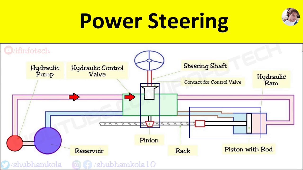
Alright, let's dive into the inner workings of a hydraulic power steering (HPS) system. If you're a seasoned DIYer or just looking to understand your car a bit better, this breakdown of a typical HPS system diagram is for you. We're going to cover everything from the major components and their functions to basic troubleshooting and safety precautions. Knowing how to interpret this diagram can be invaluable for performing repairs, modifications, or even just understanding what that weird noise coming from under the hood might be.
Purpose of Understanding the HPS Diagram
Why bother understanding the HPS diagram? Well, several reasons. Firstly, it’s essential for accurate diagnosis and repair. Instead of blindly replacing parts, you can use the diagram to trace the hydraulic circuit and pinpoint the source of a leak or malfunction. Secondly, it's crucial for modifications. If you're upgrading steering components or swapping in a different power steering pump, understanding the system layout is non-negotiable. Finally, even if you're just a curious car enthusiast, it's a great way to learn about your vehicle and appreciate the engineering that goes into even a seemingly simple system.
Key Specs and Main Parts
A typical HPS system comprises several key components, each playing a vital role in assisting your steering effort. These are:
- Power Steering Pump: The heart of the system. It's typically a vane-type or gerotor pump driven by the engine via a belt (usually a serpentine belt). It draws hydraulic fluid from the reservoir and pressurizes it, providing the force needed to assist steering. Key spec: Flow rate (liters per minute or gallons per minute) at a given RPM. This determines how quickly the system responds to steering input.
- Reservoir: A container for the power steering fluid (typically a specialized hydraulic fluid). It allows for fluid expansion and contraction due to temperature changes and helps to filter out contaminants. Key spec: Capacity (liters or quarts).
- High-Pressure Hose: A reinforced hose that carries the pressurized fluid from the pump to the steering gear or rack. It's designed to withstand significant pressure. Key spec: Working pressure (PSI or Bar). Exceeding this pressure can cause the hose to burst.
- Steering Gear or Rack: This is where the hydraulic assist is actually applied. For a steering gear system (common in older vehicles and trucks), a control valve directs fluid to either side of a piston within the gear box, assisting in turning the sector shaft. For a rack-and-pinion system (common in modern cars), the control valve directs fluid to either side of a piston that is integrated into the rack, assisting its linear motion.
- Control Valve (Rotary Valve): Located within the steering gear or rack, this valve senses the driver's steering input (torque on the steering wheel) and directs the high-pressure fluid to the appropriate side of the piston. It's a critical component for providing proportional assist – more assist when you need it (low speeds, tight turns) and less when you don't (highway driving).
- Low-Pressure Return Hose: This hose carries the fluid back from the steering gear/rack to the reservoir. It's not pressurized like the high-pressure hose.
- Cooler (Optional): Some vehicles, especially those used for towing or performance driving, have a power steering fluid cooler to dissipate heat and prevent fluid degradation. This is usually a small radiator-like device.
Understanding the Symbols in the Diagram
The diagram uses standardized symbols to represent the various components and connections. Here's a breakdown:
- Solid Lines: Represent hydraulic lines carrying fluid. The thickness of the line doesn't usually indicate pressure; it's more about clarity on the diagram.
- Dashed Lines: Often represent mechanical linkages or control lines. For example, a dashed line might connect the steering column to the control valve.
- Arrows: Indicate the direction of fluid flow.
- Rectangles: Can represent various components, with internal symbols indicating their function (e.g., a pump symbol inside a rectangle).
- Circles: Often represent gauges or sensors.
- Triangles: Often indicate pressure relief valves.
The specific symbols can vary slightly between manufacturers, but the basic principles remain the same. Refer to the legend of the specific diagram you are using for accurate interpretation.
How the Hydraulic Power Steering System Works
Here's a simplified explanation of the HPS system's operation:
- The engine drives the power steering pump, which draws fluid from the reservoir and pressurizes it.
- The pressurized fluid flows through the high-pressure hose to the steering gear or rack.
- When the driver turns the steering wheel, the control valve within the steering gear/rack senses the torque.
- The control valve directs the high-pressure fluid to either side of the piston in the steering gear/rack.
- The pressure on the piston assists the driver in turning the wheels.
- The fluid returns to the reservoir through the low-pressure return hose.
It's a closed-loop system, constantly circulating fluid to provide assist whenever needed. Without power steering, you'd be relying solely on your muscle power to overcome the resistance of the tires and steering geometry.
Real-World Use: Basic Troubleshooting
Understanding the HPS diagram can help you diagnose common problems:
- No Power Steering: Check the fluid level in the reservoir first. If it's low, top it off and look for leaks. If the fluid level is good, the pump might be faulty (not producing pressure) or the belt might be slipping. Check the belt tension and condition.
- Whining Noise: Often indicates low fluid level or air in the system. Check for leaks and bleed the system if necessary. A worn-out pump can also whine.
- Hard Steering in One Direction: Could indicate a problem with the control valve or a blockage in one of the hydraulic lines. Use the diagram to trace the circuit and check for obstructions.
- Leaks: The diagram helps you identify the source of the leak. Common leak points include the pump, hoses, and steering gear/rack seals.
Important: When diagnosing power steering problems, always start with the simplest checks first – fluid level, belt condition, hose connections.
Safety Precautions
Working with hydraulic systems involves some inherent risks:
- High Pressure: The high-pressure hose can contain fluid at extremely high pressure. Never disconnect a pressurized hose. Always relieve the pressure before disconnecting any lines.
- Hot Fluid: Power steering fluid can get very hot, especially after extended driving. Allow the system to cool down before working on it.
- Eye Protection: Wear safety glasses when working with hydraulic systems to protect your eyes from fluid splashes.
- Fluid Compatibility: Always use the correct type of power steering fluid specified for your vehicle. Using the wrong fluid can damage the system.
The pump and high-pressure lines are the riskiest components. Treat them with respect and follow all safety precautions.
By now you should have a solid foundational understanding of hydraulic power steering systems and how to interpret their diagrams. This knowledge will prove invaluable for repairs, modifications, or simply gaining a deeper appreciation for automotive engineering.