Ignition Coil Ballast Resistor Wiring Diagram
So, you're diving into the world of ignition coil ballast resistors, huh? Good on you! Whether you're restoring a classic, troubleshooting a sputtering engine, or simply deepening your automotive knowledge, understanding the wiring diagram for a ballast resistor is crucial. This article will demystify those lines and symbols, providing you with a solid foundation for tackling ignition system projects. We'll cover everything from the resistor's purpose to real-world troubleshooting, always keeping safety in mind. And the best part? We have a detailed wiring diagram available for you to download at the end of this article, making your project even easier!
Purpose of the Ballast Resistor
Let's start with the "why." Why is this resistor even there in the first place? The primary purpose of a ballast resistor is to limit the current flowing through the ignition coil during normal engine operation. Think of it as a gatekeeper, preventing the coil from overheating and failing prematurely. Here’s the breakdown:
- Cold Cranking: When you first start your engine, the starter motor draws a massive amount of current, reducing the voltage available to the ignition system. Without a ballast resistor bypass during cranking, the coil wouldn’t receive enough voltage to produce a strong spark. Many systems bypass the resistor during cranking, providing the coil with a full 12 volts (or slightly less depending on battery state).
- Normal Operation: Once the engine is running, the alternator replenishes the voltage, and the full 12+ volts would cook the coil if continuously applied. The ballast resistor steps in to reduce the voltage to the coil, typically around 8-9 volts, preventing overheating and extending coil life.
In essence, the ballast resistor allows for a hotter spark during starting (for better cold starts) and protects the coil during running (for reliability).
Key Specs and Main Parts
Before we jump into the wiring, let's identify the key components and their specifications:
- Ballast Resistor: This is the star of the show! It's a resistor, typically a ceramic block with wire windings, designed to drop voltage. Its resistance is measured in ohms (Ω), and the specific value is crucial for proper operation. Typical resistance values range from 0.8 to 1.8 ohms, but always consult your vehicle's service manual for the correct value. An incorrect value can lead to a weak spark or a burned-out coil.
- Ignition Coil: This is an induction coil that transforms the low voltage from the battery into the high voltage needed to create a spark at the spark plugs. Its primary winding resistance and inductance are important parameters, and they're designed to work in conjunction with the ballast resistor.
- Ignition Switch: This controls the flow of power to the ignition system. It typically has several positions: OFF, ACC (accessory), ON (run), and START (crank).
- Starter Solenoid (or Relay): This is a high-current switch that engages the starter motor. It often has a terminal (usually labeled "I" or "S") that provides a full 12 volts to the ignition coil during cranking, bypassing the ballast resistor.
- Distributor (or Electronic Ignition Module): This controls the timing of the spark and triggers the ignition coil to fire. In older systems, this is a mechanical distributor with points. Newer systems use electronic ignition modules.
Symbols on the Wiring Diagram
Understanding the symbols on the wiring diagram is key to tracing the circuit. Here's a breakdown of common symbols:
- Solid Lines: These represent wires connecting components. The thickness of the line doesn't usually indicate wire gauge, but it can. Typically the legend explains this, if it exists.
- Dashed Lines: These often indicate wires or connections that are part of a harness or are shielded.
- Colors: Wire colors are critical for identification. The wiring diagram will have a legend explaining the color codes. Common colors include red (power), black (ground), and various other colors for specific circuits.
- Resistor Symbol: A jagged line represents a resistor. In this case, the ballast resistor.
- Coil Symbol: A coil symbol represents the ignition coil. It usually shows the primary and secondary windings.
- Switch Symbol: Represents the ignition switch. It will show the different positions (OFF, ACC, ON, START) and the corresponding connections.
- Ground Symbol: Indicates a connection to the vehicle's chassis, which serves as the ground.
- Numbers/Labels: Wires and terminals are often labeled with numbers or letters for easy identification.
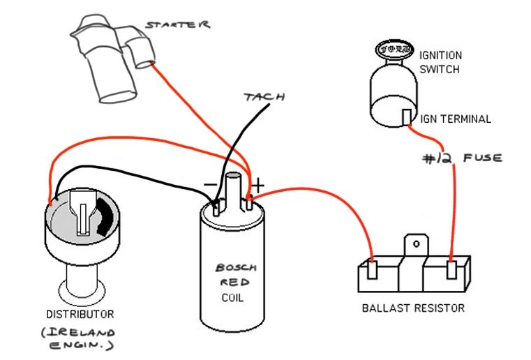
How It Works: A Circuit Walkthrough
Let's trace the flow of electricity through the ignition system, focusing on the ballast resistor's role:
- Key in the "ON" position: Power flows from the battery, through the ignition switch, and to one side of the ballast resistor.
- Voltage Drop: The ballast resistor reduces the voltage, typically to around 8-9 volts.
- Coil Input: The reduced voltage is then fed to the positive (+) terminal of the ignition coil.
- Coil Operation: The ignition coil uses this voltage to build up a magnetic field in its primary winding. When the distributor (or electronic ignition module) triggers the coil, the magnetic field collapses, inducing a high-voltage spark in the secondary winding.
- Spark Plugs: The high-voltage spark is then sent to the spark plugs, igniting the air-fuel mixture in the cylinders.
- Cranking Bypass: When the key is in the "START" position, power is also sent from the starter solenoid (or relay) directly to the positive (+) terminal of the ignition coil, bypassing the ballast resistor. This ensures the coil receives full voltage for a strong spark during cranking.
Real-World Use: Troubleshooting Tips
Here are some common problems and how to troubleshoot them using your understanding of the ballast resistor circuit:
- Engine starts but dies when you release the key from "START": This often indicates a faulty ballast resistor or a problem with the bypass circuit. The coil is getting full voltage during cranking but isn't getting any (or enough) voltage when the key is in the "ON" position. Use a multimeter to check the voltage at the coil with the key in the "ON" position. It should be around 8-9 volts. Also, check the continuity of the ballast resistor. A broken resistor will have infinite resistance (open circuit).
- Weak spark or no spark: Several factors can cause this, but the ballast resistor is a prime suspect. A resistor with too much resistance will weaken the spark. Check the resistance of the ballast resistor with a multimeter and compare it to the specification in your vehicle's service manual.
- Burnt Ignition Coil: This can be caused by a missing or bypassed ballast resistor, or a resistor with too little resistance. Without the resistor, the coil receives too much voltage and overheats.
Safety First!
Working with electrical systems can be dangerous. Always disconnect the negative battery cable before working on the ignition system. The high voltage generated by the ignition coil can be lethal. Never touch the spark plug wires or the ignition coil while the engine is running or being cranked. Be careful when handling the ballast resistor, as it can get very hot during operation. Allow it to cool down before touching it.
Ready to Dive Deeper?
Now that you have a solid understanding of the ignition coil ballast resistor wiring diagram, you're well-equipped to tackle your automotive projects with confidence. Remember to consult your vehicle's service manual for specific wiring diagrams and component values. And as promised, we have a detailed wiring diagram available for you. You can download it by clicking on the link below. Good luck with your project!
Note: Always consult a qualified mechanic if you are unsure about any aspect of the ignition system or electrical troubleshooting. Incorrect repairs can be dangerous and can damage your vehicle.
Now go forth and conquer your automotive challenges!