
Ignition Coil Wiring Harness Replacement
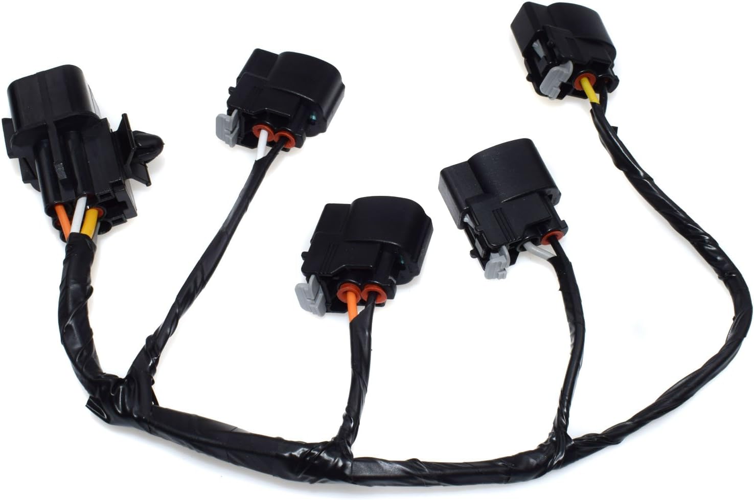
Replacing an ignition coil wiring harness can seem daunting, but with a systematic approach and a good understanding of the components involved, it's a task well within the reach of an experienced DIYer. This article provides a detailed breakdown of the process, covering everything from understanding the purpose of the harness to troubleshooting common issues.
Purpose of an Ignition Coil Wiring Harness Diagram
An ignition coil wiring harness diagram is your roadmap when working on your vehicle's ignition system. Its primary purpose is to illustrate the connections between the Engine Control Unit (ECU), the ignition coils, and other relevant sensors and components. Why is this important? Because:
- Repairs: When diagnosing misfires, replacing damaged wiring, or troubleshooting electrical issues within the ignition system, the diagram is essential for identifying the correct wires and connections.
- Modifications: Upgrading ignition coils or adding aftermarket components requires a clear understanding of the existing wiring configuration. A diagram prevents accidental shorts and ensures proper integration.
- Learning: Even if you don't plan on performing immediate repairs, studying the diagram provides a deeper understanding of how your vehicle's ignition system functions.
- Preventing Issues: Sometimes the wiring harness itself can be the source of the problem, with corroded connectors or brittle insulation. A diagram will assist in systematically checking each connection.
Key Specs and Main Parts of the Ignition System
Before diving into the specifics of the wiring harness, let's review the main components of a typical ignition system. Keep in mind that systems can vary depending on vehicle make and model, but the core principles remain the same.
- Battery: The primary power source for the entire electrical system, typically 12V DC.
- Ignition Switch: Controls the flow of power to the ignition system when the key is turned.
- Engine Control Unit (ECU): The "brain" of the engine. It monitors various sensors and controls the timing and duration of the ignition spark.
- Ignition Coils: Step-up transformers that convert the relatively low voltage from the battery into the high voltage (thousands of volts) required to create a spark at the spark plugs. Modern vehicles often use a coil-on-plug (COP) system, where each spark plug has its own dedicated ignition coil.
- Spark Plugs: Devices that ignite the air-fuel mixture in the combustion chamber.
- Crankshaft Position Sensor (CKP): Provides the ECU with information about the crankshaft's position and speed, allowing it to accurately time the spark.
- Camshaft Position Sensor (CMP): Provides the ECU with information about the camshaft's position, crucial for identifying the correct cylinder to fire in sequential fuel injection systems.
- Ignition Coil Wiring Harness: The collection of wires and connectors that connect the ECU to the ignition coils. It carries both power and control signals.
Key Specs to consider:
- Wire Gauge: Thicker wires handle more current. Make sure replacements are the correct gauge (usually AWG).
- Voltage Rating: The insulation must withstand the high voltages present in the ignition system.
- Connector Type: Match the connectors exactly to ensure a secure and reliable connection.
- Resistance: A multi-meter is needed to test resistance in the wiring system.
Understanding Ignition System Wiring Diagram Symbols
Wiring diagrams use standardized symbols to represent electrical components and connections. Here's a breakdown of some common symbols:
- Solid Lines: Represent wires. Thicker lines often indicate wires carrying higher current.
- Dashed Lines: Can represent shielded cables or wires that are not directly part of the ignition coil circuit but are related.
- Circles with numbers or letters: Indicate connectors, with the number or letter identifying the specific connector.
- Squares or Rectangles: Represent electronic components like relays, fuses, or the ECU.
- Zigzag Lines: Represent resistors or other components that impede the flow of current.
- Ground Symbol: Indicates a connection to the vehicle's chassis ground.
- Color Codes: Wires are typically color-coded, and the diagram will use abbreviations (e.g., BLK for black, RED for red, GRN for green). These color codes are crucial for identifying the correct wires.
Example: A solid line (BLK/WHT) connecting the ECU to an ignition coil, terminated with a circle labeled "C205," indicates a black wire with a white stripe connecting to connector C205 on the ignition coil.
How It Works: From ECU to Spark Plug
The ignition system works by precisely timing the delivery of a high-voltage spark to the spark plugs. Here's a simplified overview of the process:
- The ECU receives signals from the CKP and CMP sensors, determining the crankshaft and camshaft positions.
- Based on this information, along with data from other sensors (e.g., throttle position sensor, manifold absolute pressure sensor), the ECU calculates the optimal ignition timing.
- The ECU sends a low-voltage control signal to the ignition coil through the wiring harness. This signal triggers the coil to begin charging.
- At the precise moment of ignition, the ECU cuts off the control signal. This causes the magnetic field in the ignition coil to collapse rapidly.
- This rapid collapse induces a very high voltage in the secondary winding of the coil.
- This high voltage is then discharged through the spark plug, creating a spark that ignites the air-fuel mixture.
The wiring harness is the critical link that carries the control signals and power to the ignition coils. Any breaks, shorts, or corrosion in the harness can disrupt this process, leading to misfires, poor performance, or even a complete engine failure.
Real-World Use: Basic Troubleshooting
Here are some common troubleshooting scenarios involving the ignition coil wiring harness:
- Misfires: A misfire can be caused by a faulty ignition coil, a bad spark plug, or a problem with the wiring harness. Use a scan tool to identify which cylinder is misfiring. Then, inspect the wiring and connectors associated with that cylinder's ignition coil.
- No Start: If the engine cranks but doesn't start, check for spark at the spark plugs. If there's no spark, the problem could be with the ignition coil wiring harness, the ECU, or the crankshaft position sensor.
- Check Engine Light (CEL): Diagnostic trouble codes (DTCs) related to the ignition system can provide clues about the source of the problem. Use a scan tool to read the codes and consult the vehicle's service manual for troubleshooting steps. Example codes could be P0300 - Random Misfire Detected, P0351 - Ignition Coil A Primary/Secondary Circuit Malfunction
Basic Troubleshooting Steps:
- Visual Inspection: Check the wiring harness for any signs of damage, such as frayed wires, cracked insulation, or corroded connectors.
- Continuity Testing: Use a multimeter to check the continuity of each wire in the harness. Disconnect the harness from both the ECU and the ignition coils before performing this test.
- Voltage Testing: With the ignition on, use a multimeter to check for voltage at the ignition coil connectors. Refer to the wiring diagram to identify the correct pins for voltage testing.
- Resistance Testing: Test the resistance of the ignition coil itself to see if its within factory specification.
- Connector Cleaning: Clean any corroded connectors with electrical contact cleaner.
Safety Considerations
Working with the ignition system involves potentially dangerous voltages. Take the following precautions:
- Disconnect the Battery: Always disconnect the negative battery terminal before working on any electrical components.
- Wait Before Touching: After turning off the engine, wait a few minutes before touching the ignition coils or wiring. The coils can retain a residual charge.
- Use Insulated Tools: Use tools with insulated handles to prevent electric shock.
- Avoid Working in Wet Conditions: Water can increase the risk of electric shock.
Remember: The ignition coils generate extremely high voltages. Accidental contact with these voltages can be lethal. Always exercise caution and follow safety guidelines.
By understanding the purpose of the ignition coil wiring harness diagram, the key components involved, and basic troubleshooting techniques, you'll be well-equipped to diagnose and repair issues with your vehicle's ignition system. And while this article provides a general overview, always consult your vehicle's specific service manual and wiring diagrams for accurate and detailed information.
We have a detailed ignition coil wiring diagram file available. Contact us, and we'll provide you with the download link to ensure you have the right information at your fingertips when you tackle this important automotive task.