
Ignition Control Module Wiring Diagram
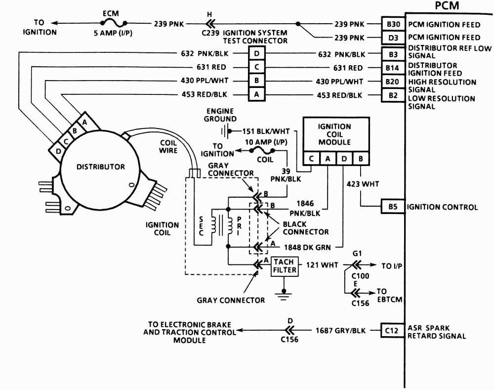
Alright, let's dive into the sometimes-intimidating but crucial world of Ignition Control Module (ICM) wiring diagrams. Understanding these diagrams is vital for anyone tackling engine repairs, modifications, or even just trying to diagnose a frustrating "no-start" condition. This isn't about becoming an automotive electrical engineer overnight, but about empowering you with the knowledge to trace circuits, identify components, and perform basic troubleshooting with confidence. And yes, to sweeten the deal, we've got a downloadable wiring diagram available for you at the end of this article – a handy reference to keep in your digital toolbox.
Purpose: Why Bother with the Diagram?
Why should you spend time deciphering squiggly lines and cryptic symbols? Because the ICM wiring diagram is your roadmap through the complex electrical system that controls when and how your engine's spark plugs fire. It's essential for:
- Diagnosis: Pinpointing electrical faults that cause misfires, no-start conditions, or poor engine performance.
- Repair: Correctly replacing damaged wiring or components within the ignition system.
- Modification: Safely integrating aftermarket components, like performance ignition coils or electronic fuel injection (EFI) systems.
- Learning: Gaining a deeper understanding of how your engine's ignition system functions.
Key Specs and Main Parts
Before we jump into the diagram itself, let's define some key components and specifications you'll encounter:
- Ignition Control Module (ICM): The brain of the ignition system. It receives signals from the engine control unit (ECU) or other sensors and controls the timing and duration of the spark events.
- Ignition Coil: A transformer that steps up the relatively low voltage from the battery to the high voltage (often 20,000-50,000 volts) needed to create a spark across the spark plug gap.
- Distributor (in older systems): A mechanical device that routes the high-voltage spark from the ignition coil to the correct spark plug at the correct time. Many modern engines use coil-on-plug (COP) or coil-near-plug (CNP) systems, eliminating the distributor.
- Crankshaft Position Sensor (CKP): A sensor that monitors the position of the crankshaft and sends this information to the ECU, which uses it to determine engine speed and crankshaft angle.
- Camshaft Position Sensor (CMP): A sensor that monitors the position of the camshaft and provides the ECU with information about valve timing.
- ECU (Engine Control Unit): The main computer in the vehicle, which manages various engine functions, including ignition timing and fuel injection. In some systems, the ECU directly controls the ignition coil firing, making the ICM redundant.
- Connectors: Physical connections between wires and components. Understanding connector pinouts is crucial for testing and troubleshooting.
- Wiring Harness: A bundle of wires that connects the various components of the ignition system.
- Grounds: Connections to the vehicle's chassis, providing a return path for electrical current. Proper grounding is essential for reliable operation.
Symbols: Decoding the Diagram
A wiring diagram uses a standardized set of symbols to represent electrical components and connections. Here's a breakdown of common symbols:
- Lines: Represent wires. Thicker lines may indicate wires carrying higher current.
- Colors: Each wire is typically identified by a color code (e.g., BLK for black, RED for red, GRN for green). These color codes are crucial for tracing wires in the vehicle.
- Circles/Dots: Indicate wire splices or connections. A solid dot typically represents a permanent connection, while an open circle may indicate a connector.
- Rectangles: Often represent components like the ICM, ECU, or relays.
- Coils (squiggly lines): Represent ignition coils, solenoids, or other inductive components.
- Resistors (zigzag lines): Represent resistors, which limit current flow.
- Capacitors (parallel lines): Represent capacitors, which store electrical energy.
- Ground symbol (a series of downward-pointing lines): Indicates a connection to the vehicle's chassis ground.
- Fuses (small rectangle with a line through it): A safety device that protects the circuit from overcurrent.
Pay attention to the *legend* or *key* on the wiring diagram. This section explains the specific symbols and abbreviations used in that particular diagram. Manufacturers sometimes use slightly different variations.
How It Works: The Ignition Sequence
Let's simplify the ignition process. The process starts with the Crankshaft Position Sensor (CKP). The CKP sends a signal to the ECU telling it the position and speed of the engine's crankshaft. The ECU, using this data (and data from other sensors like the CMP), determines the optimal time to fire the spark plugs. This signal is sent to the ICM.
The ICM then controls the primary circuit of the ignition coil. When the ICM grounds the primary side of the coil, current flows through the coil's windings, building up a magnetic field. When the ICM interrupts this current flow, the magnetic field collapses rapidly, inducing a high-voltage pulse in the coil's secondary winding. This high-voltage pulse is then sent to the spark plug, creating a spark that ignites the air-fuel mixture in the cylinder. Older distributor systems route this high voltage to the correct spark plug, whereas coil-on-plug or coil-near-plug systems each has its own coil, and is therefore controlled individually by the ECU/ICM.
The ICM's role is to act as a high-speed switch, rapidly turning the ignition coil on and off. Precise timing is absolutely critical for efficient combustion and optimal engine performance. The wiring diagram illustrates how all these components are interconnected, ensuring that the correct signals reach the ICM at the right time.
Real-World Use: Basic Troubleshooting
Okay, you've got the diagram – now what? Here are some basic troubleshooting steps:
- No-Start Condition: Use the diagram to check for voltage at the ICM. Verify that the CKP and CMP sensors are sending signals to the ECU. Check the grounds for corrosion or looseness. Use a multimeter to test the continuity of the wiring harness.
- Misfires: Identify the cylinder that's misfiring. Check the wiring to the corresponding ignition coil. Use a spark tester to verify that the coil is producing a strong spark.
- Poor Performance: Check the timing signals from the CKP and CMP sensors. Look for loose or corroded connections in the ignition system wiring.
Remember to always consult the vehicle's service manual for specific troubleshooting procedures and diagnostic trouble codes (DTCs). A scan tool can be invaluable for reading DTCs and monitoring sensor data.
Safety First!
Working with automotive electrical systems can be dangerous. Here are some crucial safety precautions:
- Disconnect the Battery: Always disconnect the negative battery terminal before working on any electrical components. This prevents accidental shorts and electrical shocks.
- High Voltage: The ignition system generates extremely high voltages. Avoid touching any ignition components while the engine is running or the ignition is turned on. Use insulated tools and wear appropriate protective gear. The ignition coil is especially risky.
- Fuel Hazards: Be aware of the risk of fuel leaks when working around the ignition system. Fuel is highly flammable. Keep sparks and open flames away.
- Consult the Manual: Always refer to the vehicle's service manual for specific safety precautions and procedures.
Always exercise caution and if you are not comfortable working with electrical systems, seek the help of a qualified mechanic.
With a good understanding of your Ignition Control Module wiring diagram, you’re ready to take on repairs, modify your car or learn more about its operation. Remember to work carefully, be sure to download your own diagram and do your own research before you begin.
Click HERE to download the Ignition Control Module Wiring Diagram.