
Ignition Harley Sportster Wiring Diagram
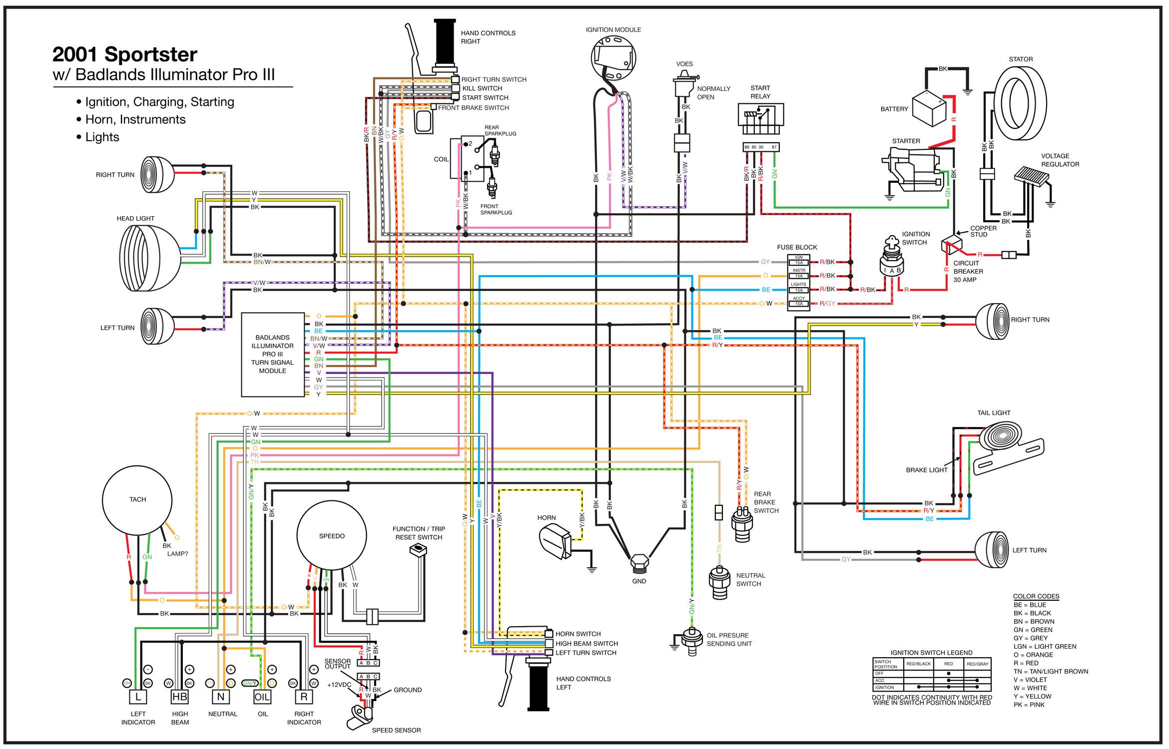
The Harley-Davidson Sportster is a quintessential motorcycle, renowned for its raw power and customizability. At some point, whether you're performing routine maintenance, troubleshooting an electrical issue, or embarking on a custom build, understanding the ignition wiring diagram for your Sportster becomes essential. This article breaks down the complexities of the ignition wiring, equipping you with the knowledge to confidently tackle electrical tasks on your bike.
Purpose of the Ignition Wiring Diagram
An ignition wiring diagram is essentially a roadmap of the electrical circuits responsible for starting and running your Sportster. It illustrates how different components are interconnected, showing the flow of electricity from the battery to the spark plugs. This diagram is invaluable for several reasons:
- Troubleshooting: When your bike refuses to start, the diagram helps you trace the electrical path, pinpointing the source of the problem – a faulty component, a broken wire, or a bad connection.
- Repairs: Need to replace a worn-out ignition coil or repair a damaged wire? The diagram ensures you reconnect everything correctly, preventing further damage.
- Customization: Planning to install aftermarket accessories, such as an electronic ignition system or a performance coil? The diagram helps you integrate the new components seamlessly into the existing wiring harness.
- Learning: Even if you don't have immediate plans for electrical work, studying the diagram provides a deeper understanding of how your motorcycle's ignition system functions.
Key Specs and Main Parts
Before diving into the diagram itself, it's important to understand the main components of a Sportster's ignition system:
Battery
The heart of the electrical system, providing the initial power to start the engine and run the accessories. Typically a 12-volt lead-acid battery.
Ignition Switch
Controls the flow of power to the ignition circuit. Turning the key to the "ON" position activates the system.
Ignition Coil
A transformer that steps up the battery's 12 volts to the high voltage needed to create a spark at the spark plugs (typically 20,000 - 50,000 volts). Sportsters often use a single-fire or dual-fire coil depending on the year and model.
Ignition Module (or Electronic Control Unit - ECU)
This electronic module controls the timing and duration of the spark. It receives signals from sensors (like the crankshaft position sensor) and triggers the ignition coil to fire at the precise moment. Older models may use a simpler ignition module compared to the more sophisticated ECUs found on newer bikes.
Crankshaft Position Sensor (CKP)
Located near the crankshaft, this sensor detects the position and speed of the crankshaft. The ECU uses this information to determine the optimal ignition timing.
Spark Plugs
The final destination of the high-voltage electricity. The spark plugs ignite the air-fuel mixture in the cylinders, initiating combustion.
Wiring Harness
The network of wires connecting all the electrical components. Each wire is typically color-coded for easy identification.
Understanding the Symbols
Wiring diagrams use standardized symbols to represent different components and connections. Here's a breakdown of some common symbols you'll encounter in a Sportster ignition wiring diagram:
- Solid Lines: Represent wires. Thicker lines may indicate wires carrying higher current.
- Dashed Lines: Often represent shielded wires or grounds.
- Circles: Can represent various components, depending on what's inside (resistors, capacitors, etc.).
- Rectangles: Typically represent switches, relays, or modules.
- Ground Symbol (usually three horizontal lines decreasing in size): Indicates a connection to the chassis ground (negative terminal of the battery).
- Color Codes: Each wire is assigned a specific color, which is indicated on the diagram (e.g., BLK for black, RED for red, BLU for blue). Refer to the legend on the diagram for the complete color code list.
Important: Always refer to the legend accompanying the diagram to understand the specific symbols and color codes used for your particular model and year.
How the Ignition System Works
The ignition system is responsible for generating the spark that ignites the air-fuel mixture in the engine's cylinders. Here's a simplified overview of how it works:
- When the ignition switch is turned "ON", power is supplied to the ignition module.
- The crankshaft position sensor detects the position of the crankshaft and sends a signal to the ignition module.
- Based on the crankshaft position and other factors (engine speed, throttle position), the ignition module determines the optimal timing for the spark.
- The ignition module then triggers the ignition coil to discharge a high-voltage pulse.
- This high-voltage pulse is sent to the spark plugs, creating a spark that ignites the air-fuel mixture.
- The combustion process drives the piston, turning the crankshaft and ultimately powering the motorcycle.
Real-World Use: Basic Troubleshooting
Let's say your Sportster won't start. Here's how the ignition wiring diagram can help you troubleshoot the issue:
- Check the basics: Ensure the battery is charged and the fuel tank is full.
- Inspect the ignition switch: Use a multimeter to check if the ignition switch is sending power to the ignition module when turned "ON". The diagram will show you which wires to test.
- Test the ignition coil: Use a multimeter to check the primary and secondary resistance of the ignition coil. The diagram may provide the expected resistance values. A reading outside the acceptable range indicates a faulty coil.
- Verify the crankshaft position sensor: Use a multimeter to check the CKP sensor's output signal. The diagram will indicate the location of the sensor and the proper testing procedure.
- Inspect the wiring harness: Look for damaged, corroded, or loose wires. Pay close attention to connectors, as they are common points of failure. The diagram helps you trace the wires and identify potential problem areas.
If you find a faulty component, replace it with a new one. If you find a damaged wire, repair it using proper splicing techniques. Always disconnect the battery before working on the electrical system.
Safety Considerations
Working with electrical systems can be dangerous. Exercise caution and follow these safety guidelines:
- Disconnect the battery: Always disconnect the negative terminal of the battery before working on the electrical system. This prevents accidental short circuits and potential electric shocks.
- High-voltage components: The ignition coil and spark plugs generate extremely high voltage. Avoid touching these components while the engine is running or the ignition system is energized. Touching these components can result in serious injury or death.
- Use appropriate tools: Use insulated tools designed for electrical work.
- Double-check your work: Before reconnecting the battery, carefully inspect your work to ensure all connections are secure and wires are properly routed.
- When in doubt, seek professional help: If you're not comfortable working on the electrical system, consult a qualified motorcycle mechanic.
Working on your motorcycle's electrical system can be a rewarding experience, allowing you to gain a deeper understanding of its inner workings. By using the ignition wiring diagram as your guide, you can confidently tackle electrical repairs, modifications, and maintenance tasks, keeping your Sportster running smoothly for years to come.
We have access to a wide variety of Sportster ignition wiring diagrams. Please reach out if you need a specific diagram for your model and year. We're happy to provide the file for you to download and use!