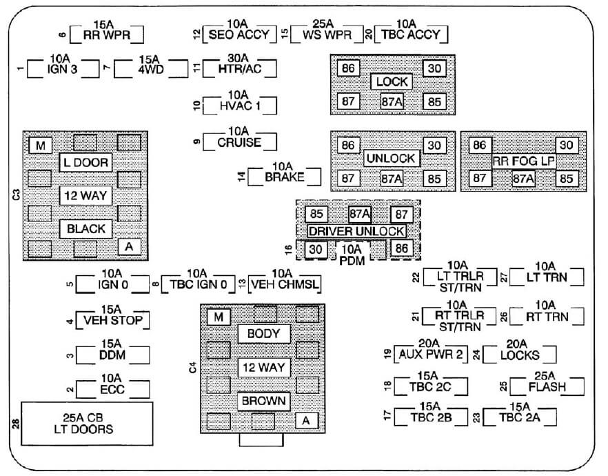
Instrument Panel 2004 Chevy Silverado Fuse Box Diagram
Hey there, fellow wrench-turners! Today, we're diving deep into the heart of your 2004 Chevy Silverado's electrical system: the instrument panel fuse box. This often-overlooked component is a crucial nerve center, protecting vital circuits and enabling everything from your radio to your windshield wipers. Understanding its layout and function can save you time, money, and frustration when tackling electrical repairs or modifications. Think of this as your decoder ring for the Silverado's electrical mysteries.
Purpose of the Instrument Panel Fuse Box Diagram
Why should you care about this diagram? Simple. It's your roadmap to resolving electrical issues. Here's why it's essential:
- Troubleshooting Electrical Problems: When something electrical goes wrong, the fuse box is the first place to check. The diagram helps you identify the specific fuse protecting the faulty circuit.
- Performing Electrical Repairs: Need to replace a blown fuse? The diagram shows you exactly which one to replace and its amperage rating.
- Installing Aftermarket Accessories: Adding a new radio, lights, or other accessories? The diagram helps you locate available circuits and properly fuse your installation to prevent damage and ensure safety.
- Understanding Your Vehicle's Electrical System: Even if you're not currently experiencing problems, studying the diagram can give you a better understanding of how your Silverado's electrical system is organized.
Key Specs and Main Parts of the Fuse Box
The instrument panel fuse box in a 2004 Chevy Silverado is typically located on the driver's side, usually behind a small access panel on the side of the dashboard. The exact location can vary slightly depending on the trim level and options. Its key components include:
- Fuse Block: This is the plastic housing that holds all the fuses and relays. It provides the physical structure and electrical connections for each circuit.
- Fuses: These are the sacrificial links that protect individual circuits from overcurrents. They come in various amperage ratings (e.g., 5A, 10A, 15A, 20A, 25A, 30A) and physical sizes (e.g., ATO, Mini, Maxi). An amperage rating is the maximum electrical current (measured in Amperes) that the fuse can safely handle before it blows.
- Relays: These are electrically operated switches that control high-current circuits using a low-current signal. They are used for components like headlights, horns, and fuel pumps. A relay essentially uses a small electrical current to control a larger one, acting as an intermediary.
- Terminal Blocks: Some circuits may use terminal blocks for connections. These are used for splicing and distributing power.
- Cover/Access Panel: This protects the fuse box and often includes a diagram showing the location and function of each fuse. However, relying *solely* on the cover diagram can be misleading; it's best to consult a more detailed diagram for accuracy.
The fuse box is designed to be relatively easy to access and maintain. Fuses can be removed and replaced using a fuse puller, which is usually located in the engine compartment fuse box or somewhere within the instrument panel area.
Decoding the Symbols: Lines, Colors, and Icons
Understanding the symbols on the fuse box diagram is crucial. Here's a breakdown of common symbols and conventions:
- Lines: These represent electrical wires and circuits. Different line thicknesses may indicate different wire gauges (thicker lines for higher current circuits).
- Colors: Wires are often color-coded to identify their function. Common colors include red (power), black (ground), and various other colors for specific circuits (e.g., blue for headlights, yellow for turn signals). The diagram will usually include a color code legend.
- Icons: These represent various electrical components. Some common icons include:
- Fuse: A zigzag line inside a rectangle.
- Relay: A rectangle with a coil symbol inside.
- Ground: A series of descending lines, resembling an upside-down tree.
- Switch: A break in a line that can be opened or closed.
- Load (e.g., light bulb, motor): A symbol representing the specific component.
- Numbers and Letters: These identify specific circuits and fuse/relay locations. For example, "IGN 1" might indicate the ignition circuit #1. "RDO" might stand for Radio, or something very similar.
- Amperage Ratings: These indicate the fuse rating (e.g., "20A" for a 20-amp fuse).
Pay close attention to the legend or key that accompanies the diagram. This will explain the meaning of specific symbols and color codes used in the diagram.
How It Works: The Electrical Flow
The fuse box acts as a central distribution point for electrical power. Power from the battery flows through the ignition switch and various other control modules before reaching the fuse box. From there, individual circuits are protected by fuses, which are designed to blow (break the circuit) if an overcurrent occurs.
When a circuit is overloaded (e.g., due to a short circuit or a faulty component), the fuse wire inside the fuse heats up rapidly and melts, interrupting the flow of current and preventing damage to the wiring and components. This sacrificial nature of the fuse is why it's so important. Without it, your wiring could melt, potentially causing a fire.
Relays allow low-current circuits (e.g., from a switch on the dashboard) to control high-current circuits (e.g., to power headlights). This prevents excessive current from flowing through the switch and protects it from damage.
Real-World Use: Basic Troubleshooting Tips
Here's how you can use the fuse box diagram to troubleshoot common electrical problems:
- Identify the Problem: Determine which electrical component is not working.
- Consult the Diagram: Locate the fuse or relay that corresponds to the faulty component.
- Inspect the Fuse: Remove the fuse and visually inspect it. If the wire inside the fuse is broken or blackened, the fuse is blown. A multimeter can be used to test a fuse for continuity. A multimeter is an electronic device used to measure voltage, current, and resistance.
- Replace the Fuse: Replace the blown fuse with a new fuse of the *exact* same amperage rating. Never use a fuse with a higher amperage rating, as this could damage the circuit and create a fire hazard.
- Test the Circuit: After replacing the fuse, test the circuit to see if the problem is resolved. If the fuse blows again immediately, there is a short circuit or other problem in the circuit that needs to be investigated further.
- Check the Relay: If the fuse is good but the component still doesn't work, the relay may be faulty. Relays can be tested using a multimeter or by swapping them with a known-good relay.
Example: Your radio suddenly stops working. You consult the fuse box diagram and identify the fuse labeled "Radio" or "RDO". You remove the fuse and find that it is blown. You replace it with a new fuse of the same amperage rating, and the radio starts working again. Problem solved!
Safety Considerations: Handle with Care
Working with electrical systems can be dangerous. Here are some important safety precautions:
- Disconnect the Battery: Before working on any electrical components, disconnect the negative terminal of the battery to prevent accidental shorts or shocks.
- Use Proper Tools: Use insulated tools designed for electrical work.
- Never Bypass a Fuse: Never replace a blown fuse with a wire or other conductive material. This can overload the circuit and create a fire hazard.
- Be Aware of High-Current Circuits: Some circuits, such as those for the starter motor and alternator, carry high currents and can be dangerous if not handled properly.
- If in Doubt, Consult a Professional: If you are not comfortable working with electrical systems, consult a qualified mechanic or electrician.
Warning: The SRS (Supplemental Restraint System), commonly known as the airbag system, utilizes high-voltage capacitors that can retain a charge even after the battery is disconnected. Improper handling of SRS components can result in serious injury. Consult a qualified technician before working on or near any SRS components.
Understanding your 2004 Chevy Silverado's instrument panel fuse box is a powerful tool. It empowers you to diagnose and fix electrical problems, install accessories safely, and gain a deeper understanding of your vehicle's systems. Remember to always prioritize safety and consult a professional if you're unsure about anything. Happy wrenching!
We have access to a detailed, high-resolution diagram of the 2004 Chevy Silverado instrument panel fuse box. If you need it, [link to download diagram here - placeholder - actual link would go here]. This diagram will provide you with the specific fuse and relay locations, amperage ratings, and circuit descriptions you need for successful troubleshooting and repairs.