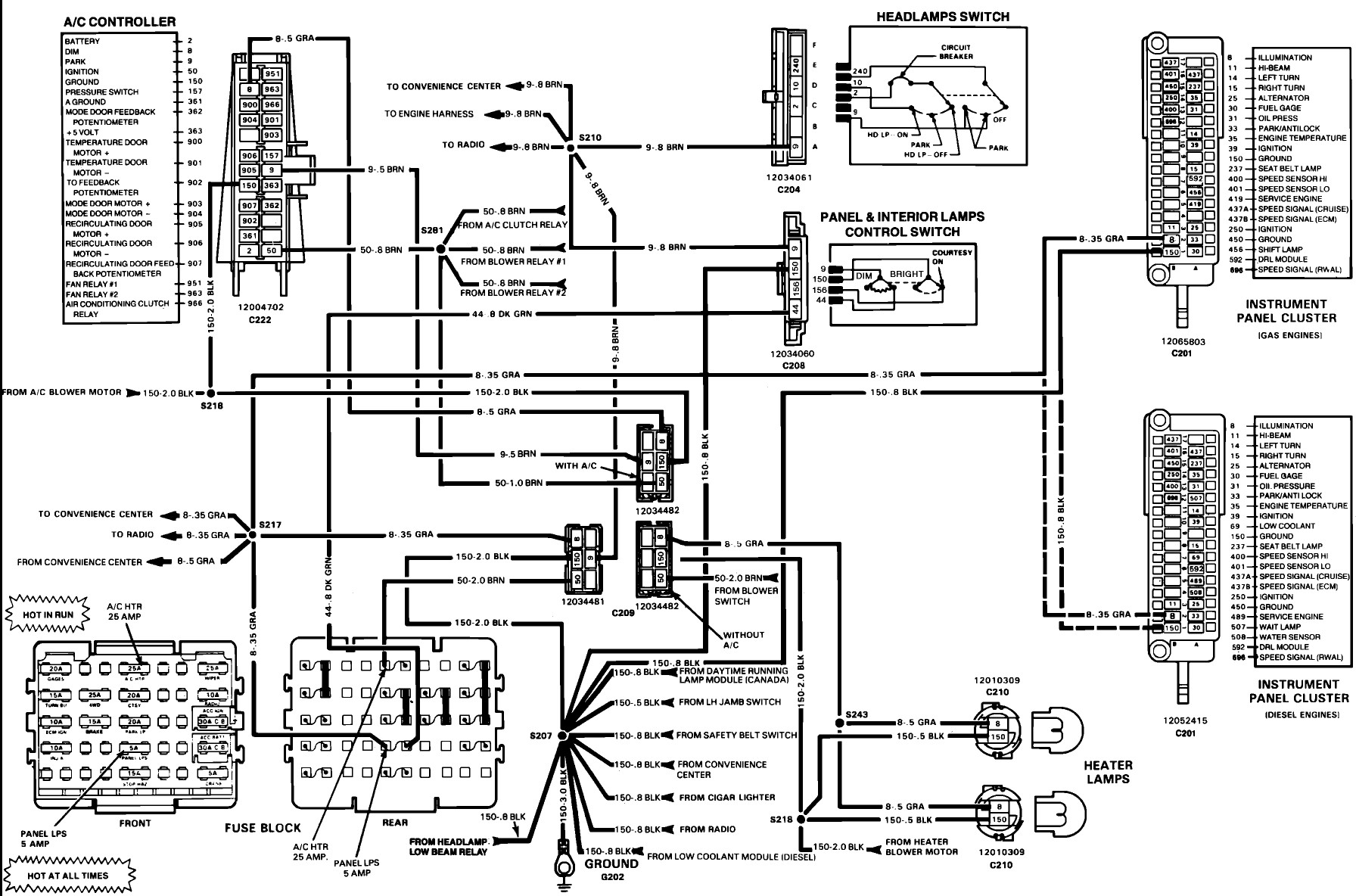
Instrument Panel 73 87 Chevy Truck Instrument Cluster Wiring Diagram
For the seasoned DIYer or aspiring auto electrician tackling a 1973-1987 Chevy truck, the instrument cluster wiring diagram is nothing short of essential. Whether you're chasing down a faulty gauge, planning a custom modification, or simply trying to understand how the system ticks, this document is your roadmap. This article will walk you through interpreting the diagram, understanding its components, and applying that knowledge in a real-world context.
Purpose of the 73-87 Chevy Truck Instrument Cluster Wiring Diagram
The instrument cluster wiring diagram serves several crucial purposes:
- Troubleshooting Electrical Issues: Pinpointing the source of problems like a non-functional speedometer, temperature gauge, or warning light. Instead of blindly replacing components, the diagram allows you to systematically test circuits.
- Repairing Damaged Wiring: Identifying damaged wires, connectors, and circuits after an accident or due to age-related degradation. The diagram shows the original routing and connections, aiding in accurate repairs.
- Modifying the Instrument Cluster: Adding aftermarket gauges, integrating new warning lights, or performing custom modifications requires a clear understanding of the existing wiring. The diagram provides the foundation for safe and effective modifications.
- Understanding Vehicle Electronics: For anyone wanting a deeper understanding of automotive electrical systems, studying the instrument cluster wiring diagram provides valuable insight into how sensors, circuits, and the vehicle's electrical system interact.
Key Specs and Main Parts of the Instrument Cluster
Before diving into the diagram itself, let's review some key specs and components of the 1973-1987 Chevy truck instrument cluster. The specific cluster configuration varied slightly depending on the year, model, and trim level, but the fundamental components remained consistent.
Key Components:
- Speedometer: Measures and displays vehicle speed. Usually mechanically driven by a cable connected to the transmission.
- Fuel Gauge: Indicates the amount of fuel remaining in the tank. Reads resistance from the fuel sending unit in the tank.
- Temperature Gauge: Displays the engine coolant temperature. Receives data from a temperature sensor in the engine.
- Oil Pressure Gauge (or Warning Light): Indicates engine oil pressure. Uses an oil pressure sensor/sending unit. Some models may use a simple oil pressure switch that only triggers a warning light when pressure is critically low.
- Ammeter (or Voltmeter): Measures the current flowing into or out of the battery (ammeter) or the voltage of the electrical system (voltmeter).
- Warning Lights: Various lights for low fuel, high beam, brake, and other critical system alerts.
- Turn Signal Indicators: Lights that blink in sync with the turn signals.
- Illumination Bulbs: Provide backlighting for the gauges and indicators.
- Printed Circuit Board: A flexible circuit board that connects all the components on the cluster. Often a point of failure due to age and heat.
- Connectors: Multi-pin connectors that interface the instrument cluster with the vehicle's wiring harness.
Key Specifications:
- Voltage: Typically 12V DC, the standard voltage for automotive electrical systems.
- Fuses: Various fuses protect the instrument cluster circuits from overcurrent. The specific fuse locations and amperage ratings are crucial for proper operation and safety. Refer to the vehicle's owner's manual or a separate fuse diagram.
- Ground Connections: Solid ground connections are essential for proper gauge and indicator function. Poor grounds are a common source of instrument cluster problems.
Understanding Wiring Diagram Symbols
Wiring diagrams use standardized symbols to represent electrical components and connections. Understanding these symbols is key to deciphering the diagram.
- Lines: Lines represent wires. Thicker lines might indicate wires carrying higher current.
- Colors: Wires are color-coded to aid in identification. The diagram will have a key indicating what each color represents (e.g., RED for battery power, BLACK for ground, etc.).
- Circles: Circles often represent terminals or connection points.
- Rectangles: Rectangles typically represent components like gauges, sensors, or switches.
- Ground Symbol: A symbol resembling a downward-pointing tree or a series of parallel lines represents a ground connection.
- Fuse Symbol: A wavy line inside a rectangle indicates a fuse.
- Connector Symbol: Often represented by a circle divided into sections, indicating a multi-pin connector.
Pay close attention to the wire colors and gauge numbers, as these are critical for identifying the correct wires in the vehicle's harness. The diagram will also show the destination of each wire, indicating which component or circuit it connects to.
How the Instrument Cluster Works
The instrument cluster receives signals from various sensors and the vehicle's electrical system to display information to the driver. Here's a simplified overview:
- Power Distribution: The instrument cluster receives power (typically 12V) from the vehicle's battery through a fuse. This power is distributed to the various gauges, lights, and circuits within the cluster.
- Sensor Inputs: Sensors like the fuel sending unit, temperature sensor, and oil pressure sensor send signals to the instrument cluster. These signals are usually in the form of varying resistance or voltage.
- Gauge Operation: The gauges convert the electrical signals from the sensors into visual readings. For example, the fuel gauge interprets the resistance from the fuel sending unit to display the fuel level. Many of these gauges operate on a bimetallic strip principle where heat generated by current flow bends the strip to move the needle.
- Warning Light Activation: Warning lights are triggered by switches or sensors that close a circuit when a specific condition is met (e.g., low oil pressure, high coolant temperature).
- Grounding: All components within the instrument cluster require a good ground connection to function properly. The ground provides a return path for the electrical current.
The printed circuit board plays a critical role in connecting all these components. Over time, the circuit board can develop cracks or corrosion, leading to intermittent or complete failure of gauges and lights.
Real-World Use: Basic Troubleshooting Tips
Here are some basic troubleshooting tips using the wiring diagram:
- No Power to Cluster: Check the fuse(s) for the instrument cluster. If the fuse is blown, replace it. If it blows again immediately, there's likely a short circuit in the wiring. Use the diagram to trace the power wire and look for any damaged insulation or pinched wires.
- Gauge Not Working: Use a multimeter to check for voltage at the gauge's power terminal. If there's no voltage, trace the power wire back to the fuse box or ignition switch. If there is voltage, check the ground connection for the gauge. Finally, test the sensor and the wiring between the sensor and the gauge. The diagram will show the correct pin assignments and wire colors.
- Warning Light Stays On: Disconnect the sensor associated with the warning light. If the light turns off, the sensor is likely faulty. If the light stays on, there's a short circuit in the wiring between the sensor and the instrument cluster.
- Intermittent Problems: Intermittent problems are often caused by loose connections or cracked circuit boards. Carefully inspect the connectors and the circuit board for any signs of damage. Use a contact cleaner to clean the connectors.
When diagnosing issues, always start with the simplest checks first: fuses, grounds, and connectors.
Safety Precautions
Working with automotive electrical systems can be dangerous. Always observe the following safety precautions:
- Disconnect the Battery: Before working on any electrical circuits, disconnect the negative battery cable to prevent accidental shorts and electric shock.
- Handle Fuses Carefully: Use the correct amperage fuse for the circuit. Using a higher amperage fuse can overload the circuit and cause a fire.
- Be Mindful of the Airbag System: Some models may have airbags. Be extremely careful when working near the airbag system, as accidental deployment can cause serious injury. Consult the vehicle's service manual for specific instructions on disabling the airbag system.
- Avoid Working in Wet Conditions: Water can conduct electricity, increasing the risk of electric shock.
- Use Proper Tools: Use insulated tools designed for automotive electrical work.
Remember, the ignition coil and condenser can store a high voltage charge even after the engine is turned off. Avoid touching these components until they have been properly discharged.
Having a clear understanding of the 1973-1987 Chevy truck instrument cluster wiring diagram is a huge asset for any DIY mechanic. With this knowledge, you can confidently tackle electrical repairs, modifications, and upgrades.
We have the file with the complete and downloadable wiring diagram available for you. Use it wisely, and happy wrenching!