
Intake Air Temperature Sensor Diagram
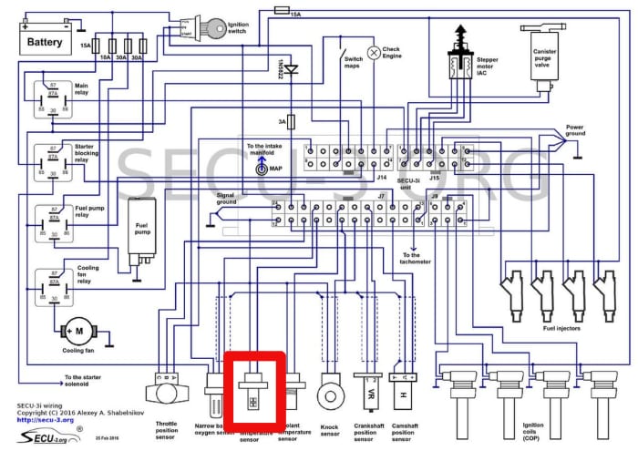
Alright, let's dive into the fascinating world of Intake Air Temperature (IAT) sensors and, more importantly, the diagrams that help us understand, diagnose, and sometimes even modify them. If you're a seasoned DIYer, a budding modder, or simply someone who wants to understand your car a little better, grasping the IAT sensor diagram is crucial. It's your roadmap to a critical component in your engine's management system.
Purpose: Why You Need This Diagram
Think of the IAT sensor diagram as the Rosetta Stone for your car's air intake system. Here’s why it's vital:
- Troubleshooting: When your engine is running rough, throwing a code related to air intake, or experiencing poor fuel economy, the IAT sensor is a prime suspect. The diagram allows you to trace the wiring, test connections, and pinpoint the exact location of a fault.
- Repairs: Replacing an IAT sensor might seem simple, but understanding the wiring diagram ensures you're connecting it correctly, avoiding short circuits, and ensuring proper functionality.
- Modifications: Planning to install an aftermarket air intake system or upgrade your ECU? The IAT sensor data is crucial for tuning the engine for optimal performance. The diagram lets you understand how the sensor interacts with the ECU and other components.
- Learning: Simply put, understanding the IAT sensor and its circuit enhances your overall knowledge of engine management systems. It builds a foundation for tackling more complex automotive diagnostics in the future.
Key Specs and Main Parts
Before we decipher the diagram, let's cover the basics of the IAT sensor itself.
- The IAT Sensor: This is a thermistor, a type of resistor whose resistance changes significantly with temperature. As the intake air temperature rises, the resistance decreases, and vice versa. This change in resistance is what the ECU reads.
- Connector: The connector is how the IAT sensor interfaces with the vehicle's wiring harness. Typically, it has two or three pins.
- Wiring: Usually, there are two wires: a signal wire (carrying the voltage signal back to the ECU) and a ground wire. Some IAT sensors, especially older ones, may use a three-wire configuration, including a reference voltage (typically 5V) from the ECU.
- Location: IAT sensors are usually located in the air intake duct, air filter housing, or intake manifold. Placement is crucial for accurate temperature readings.
Key Specs to Look For:
- Resistance Range: Knowing the resistance range of your IAT sensor at different temperatures is critical for testing. The service manual for your specific vehicle will provide this information. Typical resistance values might range from a few thousand ohms at low temperatures to a few hundred ohms at high temperatures.
- Voltage Range: The ECU typically provides a 5V reference voltage. The IAT sensor’s output voltage changes based on the air temperature. Knowing the expected voltage range at different temperatures is essential for diagnosis.
Symbols: Deciphering the Diagram
Understanding the symbols on the IAT sensor diagram is paramount. These diagrams are standardized, but variations exist across manufacturers. Here are the most common elements:
- Lines: Solid lines represent wires. Dashed lines often indicate shielded wires, which are used to prevent electromagnetic interference (EMI) from affecting the signal.
- Colors: Wire colors are usually labeled on the diagram using abbreviations (e.g., BLK for black, RED for red, GRN for green). Matching the wire colors on the diagram to the actual wires in your car is essential for proper diagnosis and repair.
- Ground Symbols: Typically, a ground symbol looks like a series of descending horizontal lines or an inverted triangle. It indicates where the circuit is grounded to the vehicle's chassis.
- Connectors: Connectors are usually represented by squares or rectangles with pin numbers inside. The diagram will show which wire connects to which pin on the connector.
- ECU/PCM: The Engine Control Unit (ECU) or Powertrain Control Module (PCM) is often represented by a larger rectangle or box, with multiple input/output pins. The IAT sensor signal wire will connect to a specific pin on the ECU/PCM.
- Resistors: Resistors are depicted by a jagged line. In the context of an IAT sensor, the thermistor itself may be represented by a resistor symbol, though often the entire sensor is shown as a labeled box.
Important: Some diagrams use letter codes to identify wires and components. Consult your vehicle's service manual for a comprehensive list of these codes.
How It Works: The IAT Sensor Circuit
The IAT sensor operates within a simple electrical circuit. Here's a breakdown:
- Reference Voltage: The ECU provides a stable reference voltage (typically 5V) to the IAT sensor.
- Resistance Change: As air flows past the sensor, its temperature affects the resistance of the thermistor.
- Voltage Drop: The voltage drop across the thermistor changes with its resistance. A higher temperature results in lower resistance and, thus, a smaller voltage drop.
- Signal to ECU: The ECU measures the voltage drop and interprets it as the intake air temperature.
- Fuel and Timing Adjustments: Based on the IAT reading, the ECU adjusts the air-fuel mixture and ignition timing to optimize engine performance and fuel efficiency. For example, colder air is denser and requires more fuel to maintain the correct air-fuel ratio.
Key Concept: The IAT sensor provides crucial data for a feedback loop. The ECU constantly monitors the IAT and adjusts engine parameters accordingly.
Real-World Use: Basic Troubleshooting
Here's how you can use the IAT sensor diagram for basic troubleshooting:
- Check for Codes: Use an OBD-II scanner to check for diagnostic trouble codes (DTCs) related to the IAT sensor (e.g., P0110, P0112, P0113).
- Locate the Sensor: Using the diagram, identify the IAT sensor's location in your vehicle.
- Visual Inspection: Inspect the sensor and its connector for any signs of damage, corrosion, or loose connections.
- Continuity Test: Use a multimeter to check the continuity of the wires between the IAT sensor connector and the ECU. Refer to the wiring diagram to identify the correct pins.
- Resistance Measurement: Disconnect the IAT sensor and measure its resistance using a multimeter. Compare the reading to the specifications in your service manual. A significantly different reading indicates a faulty sensor.
- Voltage Check: With the ignition on but the engine off, use a multimeter to check for the presence of the reference voltage at the IAT sensor connector.
Pro Tip: Before replacing the IAT sensor, double-check the wiring and connections. A faulty connection is often the culprit.
Safety: Handle with Care
Working with electrical components carries inherent risks. Here are a few safety precautions:
- Disconnect the Battery: Always disconnect the negative battery terminal before working on any electrical components. This prevents accidental short circuits and electrical shocks.
- Use Proper Tools: Use insulated tools and a multimeter with appropriate voltage and current ratings.
- Avoid Water: Never work on electrical components in wet or damp conditions.
- ECU Protection: When testing circuits, be extremely careful not to short-circuit any wires connected to the ECU. This can damage the ECU and require expensive repairs.
Warning: The ECU is a sensitive and expensive component. Take extra precautions when working near it.
With the detailed guidance here, you're well-equipped to understand and utilize IAT sensor diagrams for troubleshooting, repairs, and even performance modifications. Remember to always consult your vehicle's specific service manual for accurate wiring diagrams and technical specifications.
We have a sample IAT sensor diagram file available for download. It will help you follow the explanations given above. Contact us if you want the file.