Intake Manifold 5vz Fe Toyota 3.4 Vacuum Hose Diagram
Alright, let's dive into the intricate world of the Toyota 5VZ-FE 3.4L V6 intake manifold vacuum hose diagram. This isn't just a bunch of colored lines; it's the roadmap to your engine's breathing and overall health. Whether you're tackling a repair, chasing down a mysterious vacuum leak, or simply trying to understand how your Toyota operates, understanding this diagram is essential. We'll break it down step-by-step, so you can confidently navigate the maze of hoses and vacuum-operated systems.
Purpose: Why This Diagram Matters
The vacuum hose diagram for your 5VZ-FE serves several critical functions:
- Diagnosis and Repair: When your engine is idling rough, exhibiting poor fuel economy, or throwing diagnostic trouble codes (DTCs) related to vacuum leaks (like P0171 or P0174), the diagram is your first line of defense. It helps pinpoint the exact location of damaged, disconnected, or brittle hoses.
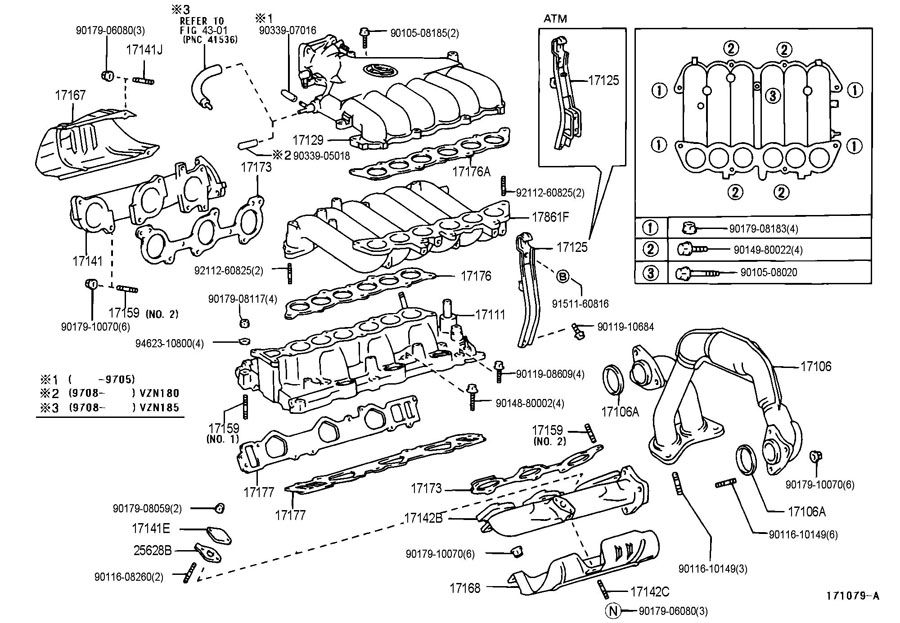
- Component Identification: The diagram clearly identifies each vacuum-operated component, such as the PCV valve, EGR valve, vacuum modulator, and fuel pressure regulator. This is invaluable when replacing parts or diagnosing a specific system.
- System Understanding: By tracing the vacuum lines, you can understand how different systems interact and rely on vacuum. For instance, seeing how the EGR valve uses vacuum to recirculate exhaust gases back into the intake manifold gives you a better grasp of emissions control.
- Restoration and Modification: If you're restoring a classic Toyota or modifying your 4Runner/Tacoma, the diagram ensures you correctly route all vacuum lines, avoiding performance issues or potential damage.
- Preventative Maintenance: Regularly inspecting vacuum hoses for cracks, hardening, or looseness, guided by the diagram, can prevent major engine problems down the road.
Key Specs and Main Parts
The 5VZ-FE vacuum system is relatively straightforward compared to some modern engines, but it still has essential components:
- Intake Manifold: The heart of the vacuum system, providing the source of vacuum pressure. It's bolted to the cylinder heads and distributes air to each cylinder.
- Throttle Body: Controls the amount of air entering the engine. A butterfly valve regulates airflow.
- PCV (Positive Crankcase Ventilation) Valve: This valve regulates the flow of crankcase gases back into the intake manifold to be burned, reducing emissions. A common source of vacuum leaks if it fails.
- EGR (Exhaust Gas Recirculation) Valve: Reduces NOx emissions by recirculating a portion of the exhaust gas back into the intake manifold.
- EGR Vacuum Modulator: Controls the amount of vacuum applied to the EGR valve based on engine load and speed.
- Fuel Pressure Regulator: Maintains a constant fuel pressure to the fuel injectors, ensuring proper fuel delivery. Vacuum influences the fuel pressure.
- Vacuum Switching Valve (VSV): Electrically controlled valves that switch vacuum between different components based on engine operating conditions.
- Charcoal Canister: Part of the evaporative emissions (EVAP) system, stores fuel vapors from the fuel tank.
- Vacuum Hoses: Connect all these components. They are typically made of rubber or silicone.
Symbols: Understanding the Diagram
Vacuum hose diagrams utilize a standard set of symbols to represent different components and connections. Let's decode them:
- Solid Lines: Typically represent vacuum hoses connecting different components.
- Dotted Lines: Often indicate electrical wiring or control signals. Pay close attention to these if you're tracing electrical problems related to vacuum-operated devices.
- Different Colors: Some diagrams use different colors to differentiate between various vacuum lines. Consult the diagram's legend to understand what each color represents. It might indicate different vacuum levels or connection to different systems.
- Arrows: Indicate the direction of vacuum flow. This is crucial when tracing a circuit and understanding how vacuum is applied to a specific component.
- Circles or Squares: Represent specific components, with abbreviations or names indicating what they are (e.g., "PCV," "EGR," "VSV").
- T-Connectors: Show where one vacuum line splits into two or more. Pay close attention to these, as they can be points of failure.
- Check Valves: Allow vacuum to flow in one direction only. They are often marked with an arrow pointing in the direction of allowed flow.
How It Works: The Vacuum Network
The 5VZ-FE engine generates vacuum within the intake manifold as the pistons move down on the intake stroke. This vacuum is then distributed throughout the engine bay via a network of hoses to operate various systems. Here's a simplified breakdown:
- The intake manifold acts as the vacuum source.
- A main vacuum line branches off from the intake manifold, feeding vacuum to various components.
- The PCV valve uses vacuum to draw crankcase gases into the intake manifold.
- The EGR valve is opened by vacuum, allowing exhaust gases to recirculate. The EGR vacuum modulator controls the amount of vacuum based on engine conditions.
- The fuel pressure regulator uses vacuum to adjust fuel pressure based on engine load.
- VSVs control the flow of vacuum to other components, such as the EVAP system.
Essentially, the engine's vacuum is a powerful and precise force that controls several important engine functions. Properly functioning vacuum systems ensure optimal engine performance, fuel efficiency, and emissions control.
Real-World Use: Basic Troubleshooting Tips
When troubleshooting vacuum-related issues, consider these tips:
- Visual Inspection: Start with a thorough visual inspection of all vacuum hoses. Look for cracks, dry rot, looseness, or kinks. This is the most common cause of vacuum leaks.
- Vacuum Leak Test: Use a vacuum gauge or a spray bottle with soapy water to identify leaks. Spray soapy water on suspected leak areas (hose connections, intake manifold gasket). If bubbles form, you've found a leak.
- Smoke Test: A smoke test is a more advanced method for finding leaks. A smoke machine introduces smoke into the vacuum system, and leaks are revealed by escaping smoke.
- Component Testing: If a specific component is suspected, test it according to the service manual. For example, test the PCV valve by shaking it – it should rattle freely. Test VSVs for proper electrical function.
- Replace Hoses: If hoses are old or questionable, replace them. Use high-quality rubber or silicone vacuum hoses.
- Check Connections: Ensure all hose connections are secure and properly seated.
Safety: Highlight Risky Components
While vacuum systems are generally safe, there are a few components to be mindful of:
- High Engine Temperatures: Be careful when working around the exhaust manifold and other hot engine components. Allow the engine to cool down before starting any work.
- Fuel Lines: Vacuum lines are sometimes routed near fuel lines. Avoid damaging fuel lines while working on vacuum systems. Fuel leaks can be extremely dangerous.
- Electrical Components: Disconnect the negative battery cable before working on electrical components related to the vacuum system, such as VSVs.
Always consult your vehicle's service manual for specific instructions and safety precautions. If you're unsure about any procedure, seek professional assistance from a qualified mechanic.
We have a detailed, downloadable vacuum hose diagram for the 5VZ-FE engine available for you. It provides a clear and comprehensive view of the entire vacuum system. This resource will be invaluable as you diagnose, repair, and maintain your Toyota's engine.