Intake Manifold Ford 4.2 Liter V6 Engine Diagram
Alright, let's dive into the intake manifold of the Ford 4.2 Liter V6 engine. This guide is designed for the intermediate DIYer, the weekend warrior who isn't afraid to get their hands dirty but appreciates a clear, concise explanation. We're going to cover everything from the purpose of a diagram to common troubleshooting tips. We'll be focusing on understanding how the intake manifold functions and how to interpret a typical diagram, so you can tackle repairs, modifications, or just expand your automotive knowledge.
Why This Diagram Matters
Think of the intake manifold as the engine's lungs. A detailed diagram is invaluable for several reasons:
- Troubleshooting: Identifying vacuum leaks, diagnosing misfires, and pinpointing sensor issues become significantly easier when you know the layout of the intake system.
- Repairs: Replacing gaskets, sensors, or even the manifold itself requires knowing where everything is located and how it connects. The diagram prevents costly mistakes and ensures proper reassembly.
- Modifications: Planning performance upgrades like cold air intakes, throttle body upgrades, or even forced induction requires a deep understanding of the intake manifold's design.
- Learning: Even if you don't plan on wrenching, understanding the intake manifold's function is crucial for grasping how your engine operates.
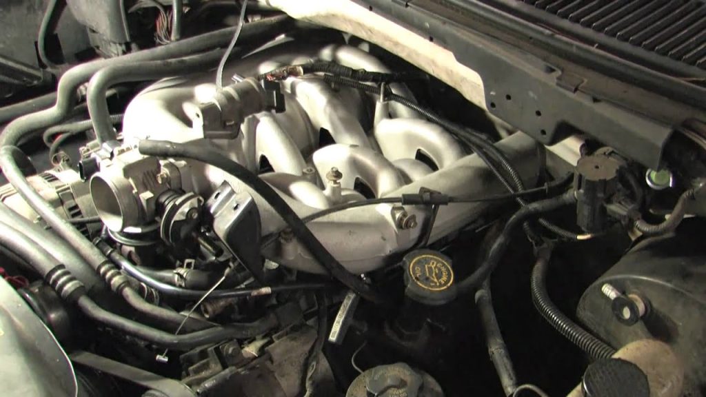
Key Specs and Main Parts
Before we jump into the diagram itself, let's review some key specs and the main components you'll encounter on the Ford 4.2L V6 intake manifold:
- Engine Displacement: 4.2 Liters (256 cubic inches)
- Engine Configuration: 90-degree V6
- Fuel Delivery: Sequential Fuel Injection (SFI) - Each cylinder has its own injector.
- Material: Typically cast aluminum or composite plastic (depending on the year and specific model).
Now, let's break down the major parts you'll see on the diagram:
- Intake Manifold Plenum: This is the main chamber that distributes air to the individual runners. Think of it as the "lungs" of the system.
- Intake Runners: These are the individual tubes that channel air from the plenum to each cylinder's intake port on the cylinder head. Their length and diameter are crucial for optimizing engine performance.
- Throttle Body: Controls the amount of air entering the engine. It contains the throttle plate, which is controlled by the accelerator pedal.
- Throttle Position Sensor (TPS): Mounted on the throttle body, it provides the engine control unit (ECU) with information about the throttle plate's position. This is vital for fuel injection control.
- Idle Air Control (IAC) Valve: Bypasses the throttle plate to maintain a stable idle speed.
- Manifold Absolute Pressure (MAP) Sensor: Measures the pressure inside the intake manifold, providing the ECU with information about engine load. This is critical for fuel mixture calculation.
- Fuel Injectors: Spray fuel into the intake ports just before the intake valves.
- Fuel Rail: Supplies fuel to the injectors.
- Vacuum Lines: Connect various components and provide vacuum sources for systems like the PCV valve, brake booster, and air conditioning controls. Vacuum leaks are a common cause of engine problems.
- Gaskets: Seals between the intake manifold and the cylinder heads, and between the manifold halves (if applicable). These are prone to leaking over time.
Decoding the Diagram: Symbols and Conventions
Understanding the symbols used in the diagram is crucial for interpreting it correctly. Here are some common conventions:
- Solid Lines: Typically represent hard lines, such as vacuum hoses, fuel lines, or coolant passages. The thickness of the line might indicate the size or type of line.
- Dashed Lines: Often indicate vacuum lines or control signals (electrical wiring) rather than physical hoses carrying fluids.
- Colors: Some diagrams use colors to distinguish different types of lines. For example, blue might represent coolant, red might represent fuel, and green might represent vacuum. Always refer to the diagram's legend for clarification.
- Arrows: Indicate the direction of flow of fluids or air.
- Geometric Shapes: Rectangles might represent sensors, circles might represent valves, and so on. Again, the diagram's legend is your friend.
- Abbreviations: Common abbreviations include "IAC" (Idle Air Control), "TPS" (Throttle Position Sensor), "MAP" (Manifold Absolute Pressure), "PCV" (Positive Crankcase Ventilation), and "EGR" (Exhaust Gas Recirculation).
Pay close attention to the legend or key that accompanies the diagram. This will provide a comprehensive explanation of the symbols and abbreviations used.
How It Works: The Intake Manifold in Action
The intake manifold's primary function is to distribute air evenly to each cylinder. Here's a simplified explanation of how it works:
- Air Intake: Air enters the engine through the air filter and flows into the throttle body.
- Throttle Control: The throttle plate, controlled by the accelerator pedal, regulates the amount of air entering the intake manifold.
- Distribution: The air flows into the intake manifold plenum and then into the individual intake runners.
- Fuel Injection: As air flows through the intake runners, fuel injectors spray fuel into the air stream. The air and fuel mix to create a combustible mixture.
- Combustion: The air-fuel mixture enters the cylinders through the intake valves, where it is compressed and ignited by the spark plug, creating the power stroke.
The ECU (Engine Control Unit) plays a critical role in this process. It monitors various sensors, such as the TPS, MAP sensor, and oxygen sensors, and adjusts the fuel injection timing and duration to optimize engine performance and emissions.
Real-World Use: Basic Troubleshooting Tips
Here are a few common problems related to the intake manifold and how a diagram can help you diagnose them:
- Vacuum Leaks: Vacuum leaks are a very common issue and can cause a rough idle, poor acceleration, and increased fuel consumption. Use the diagram to locate all vacuum lines and connections. Inspect them for cracks, leaks, or loose connections. A smoke test can be very effective in finding elusive vacuum leaks.
- Misfires: A misfire can be caused by a variety of factors, including a faulty fuel injector, a vacuum leak in an intake runner, or a problem with the ignition system. The diagram can help you isolate the misfiring cylinder and focus your troubleshooting efforts.
- Sensor Problems: If the MAP sensor or TPS is faulty, it can cause a variety of performance problems. Use the diagram to locate the sensors and check their wiring connections. You can also use a multimeter to test the sensor's output voltage.
- Gasket Leaks: A leaking intake manifold gasket can cause vacuum leaks, coolant leaks, and oil leaks. The diagram will show you the location of the gaskets and help you identify potential leak points. Look for signs of coolant or oil around the gasket surface.
Safety First!
Working on the intake manifold involves dealing with several potentially hazardous components:
- Fuel System: The fuel rail and fuel injectors are under high pressure. Always relieve fuel pressure before disconnecting any fuel lines. Work in a well-ventilated area and avoid open flames.
- Coolant System: The coolant system is also under pressure and can be hot. Allow the engine to cool down completely before disconnecting any coolant hoses.
- Electrical System: Disconnect the negative battery cable before working on any electrical components, such as sensors or wiring harnesses.
- Hot Surfaces: The engine can be very hot, especially after running. Allow the engine to cool down completely before touching any parts.
Always wear safety glasses and gloves when working on your vehicle. Consult a repair manual for specific instructions and torque specifications.
Understanding the Ford 4.2L V6 intake manifold and how to interpret a diagram is a valuable skill for any DIY mechanic. It empowers you to diagnose problems, perform repairs, and even upgrade your engine's performance. Remember to prioritize safety and consult a repair manual for detailed instructions.
We have a downloadable diagram available for your use. Click the button below to download the file and have it available as your repair!