Interior 06 Mustang 2006 Ford Mustang Fuse Box Diagram
For the intermediate car owner tackling repairs, modifications, or simply trying to understand their 2006 Ford Mustang's electrical system, the interior fuse box diagram is an invaluable tool. This isn't just a piece of paper; it's a roadmap to troubleshooting electrical issues, safely adding aftermarket accessories, and gaining a deeper understanding of your Mustang's inner workings. Forget blindly pulling fuses; let's delve into how to read and use this essential diagram.
Purpose of the Fuse Box Diagram
The fuse box diagram, specifically the one for the interior fuse box on a 2006 Ford Mustang, serves several critical purposes:
- Troubleshooting Electrical Problems: When an electrical component stops working – a light, the radio, power windows – the first place to check is the fuse box. The diagram tells you which fuse corresponds to that component, allowing you to quickly identify and replace a blown fuse.
- Installing Aftermarket Accessories: Adding things like aftermarket stereos, amplifiers, or auxiliary lighting requires tapping into the car's electrical system. The diagram helps you identify appropriate power sources and prevents you from overloading circuits.
- Understanding the Electrical System: Even if you're not actively working on your car, understanding the fuse box diagram gives you a better understanding of how the various electrical components are powered and protected.
- Preventing Damage: Replacing a fuse with one of the wrong amperage can cause serious damage to the affected component or even start a fire. The diagram ensures you use the correct fuse for each circuit.
Key Specs and Main Parts of the 2006 Mustang Interior Fuse Box
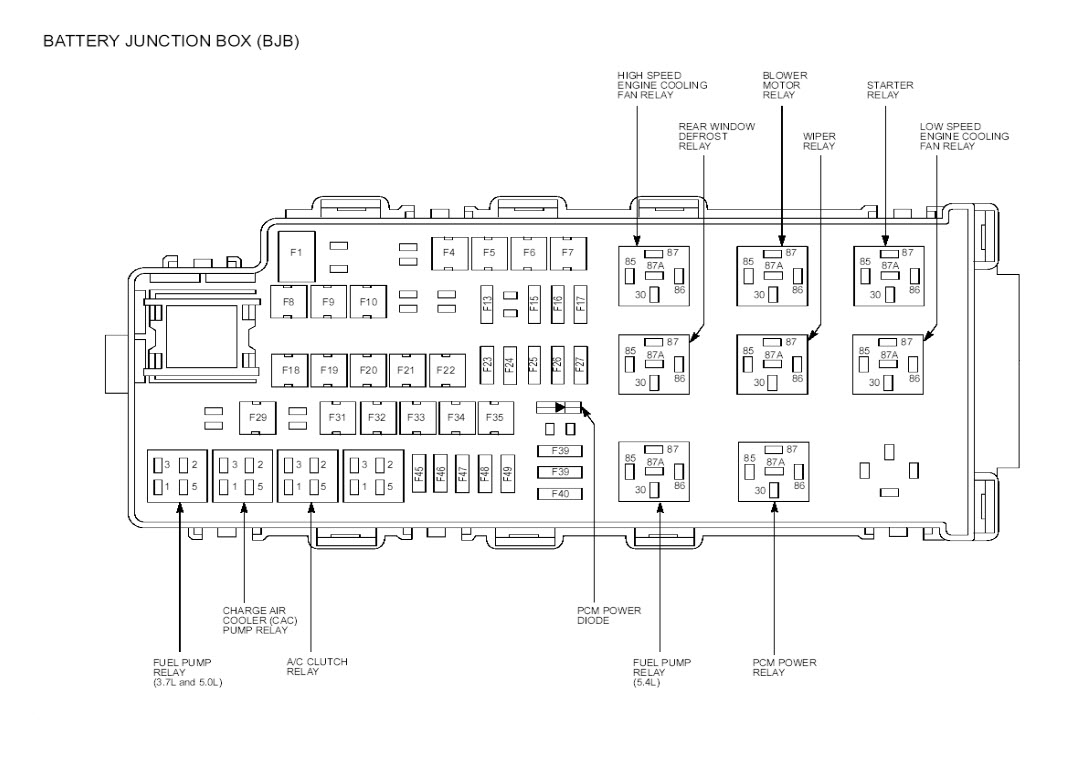
The interior fuse box on a 2006 Mustang is typically located under the dashboard, often on the driver's side. Accessing it usually involves removing a small panel or cover. The box itself contains a variety of fuses and relays. Here's a breakdown of the key elements:
- Fuses: These are the protective devices designed to break an electrical circuit if the current exceeds a safe level. They are rated in amperes (amps or A), which indicates the maximum current they can handle before blowing. Common amperage ratings include 5A, 7.5A, 10A, 15A, 20A, 25A, and 30A.
- Relays: Relays are electromechanical switches that use a small current to control a larger current. They are used to switch on high-power devices like headlights, the fuel pump, or the starter motor. They are often used in cases where the control switch cannot handle the current the system needs.
- Fuse Puller: A small plastic tool specifically designed to remove fuses from the fuse box. It makes the job easier and prevents damage to the fuse or the fuse box.
- Spare Fuses: Most fuse boxes include a selection of spare fuses of different amperage ratings. This allows you to quickly replace a blown fuse without having to run to the auto parts store.
Symbols and Legend Explained
The fuse box diagram uses a combination of lines, colors, and icons to represent different circuits and components. Understanding these symbols is crucial for interpreting the diagram correctly.
- Lines: Lines indicate the electrical circuits. A thicker line often represents a circuit carrying a higher current.
- Colors: Colors are used to differentiate between different circuits. While the specific color coding may vary slightly, common conventions include:
- Red: Typically indicates a constant power source (always hot).
- Yellow: Often indicates a switched power source (hot when the ignition is on).
- Black: Represents ground.
- Icons: Icons represent the components that are protected by the fuses. Some common icons include:
- Light Bulb: Indicates a lighting circuit (headlights, tail lights, interior lights).
- Speaker: Represents the audio system.
- Window: Indicates the power windows.
- Fan: Represents the blower motor for the climate control system.
- Cigar Lighter: Represents the auxiliary power outlet (cigarette lighter).
- Engine Symbol: Represents engine management related circuits.
The diagram will also include a legend, which is a key that explains the meaning of each symbol and color used in the diagram. Always refer to the legend to ensure you are interpreting the diagram correctly.
How It Works: From Power Source to Component
The interior fuse box acts as a central distribution point for electrical power in the cabin of your Mustang. Power from the battery (typically a 12V DC source) is fed into the fuse box, and then distributed to various components through individual circuits. Each circuit is protected by a fuse that is sized appropriately for the current draw of the component. If a component draws too much current (due to a short circuit or malfunction), the fuse will blow, interrupting the circuit and preventing damage to the component and the wiring.
Here's a simplified illustration:
- Battery supplies power to the fuse box.
- Power travels through a specific fuse (e.g., the fuse for the radio).
- If the radio draws too much current, the fuse blows, cutting off power.
- If the fuse is intact, power reaches the radio, and it functions normally.
Real-World Use: Basic Troubleshooting Tips
Here's how to use the fuse box diagram for basic troubleshooting:
- Identify the Problem: Determine which component is not working (e.g., the windshield wipers).
- Consult the Diagram: Locate the fuse that corresponds to the windshield wipers in the fuse box diagram.
- Inspect the Fuse: Visually inspect the fuse. If the metal filament inside the fuse is broken, the fuse is blown. You can also use a multimeter to test the fuse for continuity. Set the multimeter to continuity mode (it usually has a speaker icon). Place one probe on each of the metal contacts of the fuse. If the multimeter beeps, the fuse is good. If it doesn't, the fuse is blown.
- Replace the Fuse: Replace the blown fuse with a new fuse of the exact same amperage rating. Do not use a higher amperage fuse, as this could damage the component or the wiring.
- Test the Component: Turn on the component to see if it now works.
If the new fuse blows immediately, there is likely a short circuit in the wiring or a problem with the component itself. Further diagnosis is required to identify and fix the short circuit before replacing the fuse again.
Safety Considerations
Working with electrical systems can be dangerous. Here are some important safety precautions:
- Disconnect the Battery: Before working on the electrical system, disconnect the negative terminal of the battery. This will prevent accidental short circuits and electric shock.
- Use the Correct Fuse: Always replace a blown fuse with a fuse of the exact same amperage rating. Using a higher amperage fuse can overload the circuit and cause a fire.
- Be Careful with Relays: Relays can get hot during operation. Avoid touching them immediately after the car has been running.
- Never Work in Wet Conditions: Water is an excellent conductor of electricity. Never work on the electrical system in wet conditions.
- Respect High-Voltage Components: Some components, such as the ignition coil and the air conditioning compressor, operate at high voltages. Avoid touching these components unless you are specifically trained to do so.
Important Note: Some circuits, like those related to the airbags or the anti-lock braking system (ABS), are particularly sensitive. If you suspect a problem with these systems, it is best to consult a qualified mechanic.
By understanding the interior fuse box diagram and following these safety precautions, you can safely and effectively troubleshoot electrical problems, install aftermarket accessories, and gain a better understanding of your 2006 Ford Mustang's electrical system.
We have the complete interior fuse box diagram file for the 2006 Ford Mustang available for download. This detailed diagram will provide you with a precise layout and component identification for your specific model year, making your electrical troubleshooting and modification projects even easier. Download it and keep it handy for future reference.