
Jeep Gladiator Front Suspension Diagram
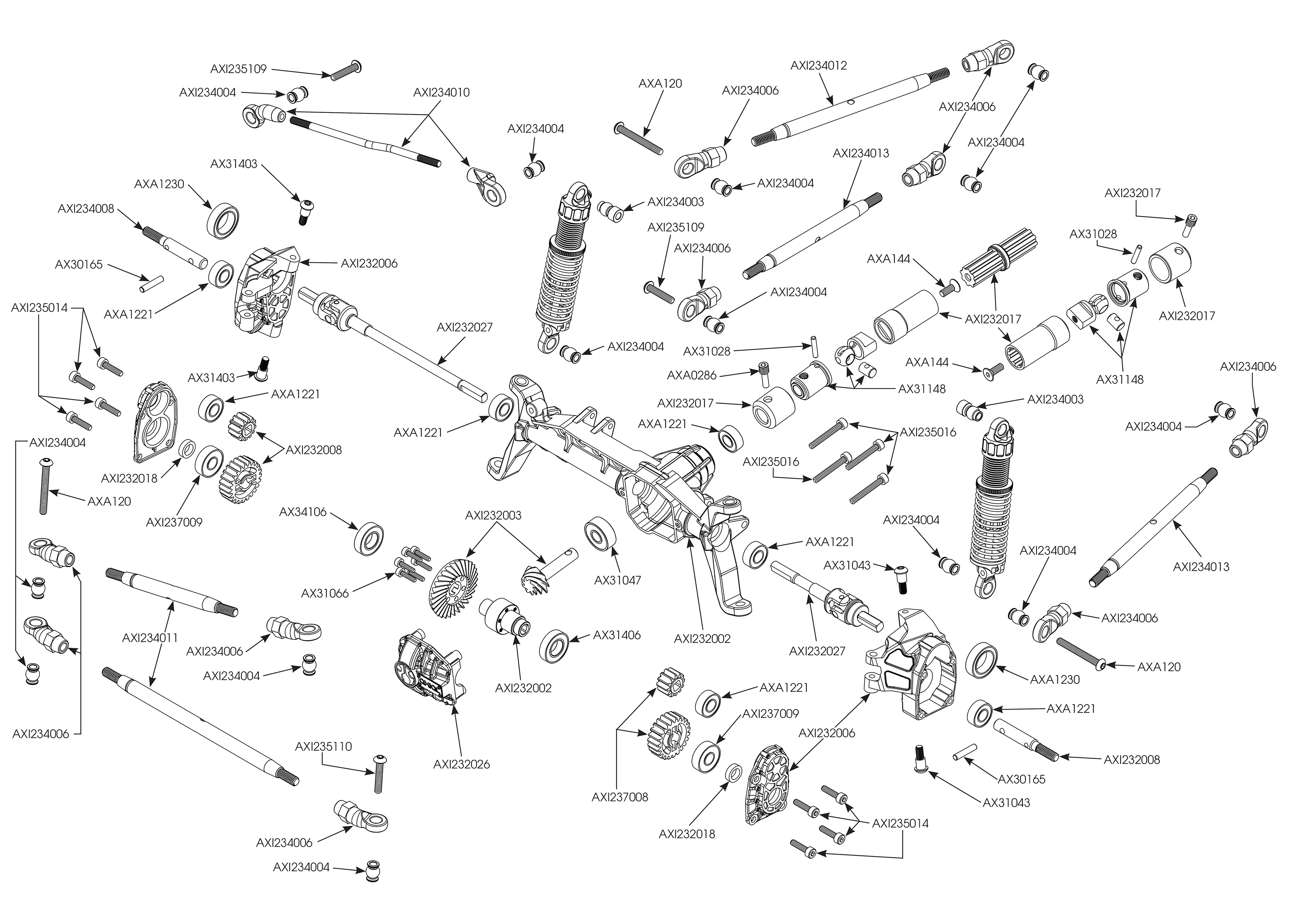
Understanding the front suspension on your Jeep Gladiator is crucial for performing maintenance, modifications, and troubleshooting issues. This guide breaks down the anatomy of the Gladiator's front suspension using a diagram, explaining key components, functionality, and providing practical advice for DIY mechanics.
Purpose of Understanding the Gladiator's Front Suspension Diagram
A detailed front suspension diagram serves multiple crucial purposes:
- Repair and Maintenance: Identifying parts for replacement, torque specs for bolts, and overall system integrity.
- Troubleshooting: Diagnosing suspension problems by visually inspecting components and understanding their relationships.
- Modifications: Planning lift kits, upgraded shocks, and other performance enhancements with a clear understanding of how they'll affect the suspension geometry.
- General Knowledge: A deeper understanding of your vehicle and its mechanics, enabling you to better communicate with professional mechanics and make informed decisions.
Key Specs and Main Parts of the Gladiator Front Suspension
The Jeep Gladiator utilizes a solid front axle, a design common in off-road vehicles due to its strength and articulation capabilities. Let's break down the main components:
- Solid Front Axle (Dana 44): The central beam connecting the front wheels. It houses the differential and axle shafts. The Dana 44 is known for its durability.
- Coil Springs: Provide vertical support and absorb shocks. The spring rate (measured in lbs/inch or N/mm) determines the stiffness and load-carrying capacity.
- Shock Absorbers (Dampers): Control the oscillation of the springs, preventing excessive bouncing. Common types include hydraulic and gas-charged shocks.
- Control Arms (Radius Arms): Two on each side, these connect the axle to the frame, controlling its movement. The upper and lower control arms work together to manage the axle's fore-aft positioning and prevent axle wrap (twisting under acceleration).
- Track Bar (Panhard Rod): Locates the axle laterally, preventing side-to-side movement. It connects the axle to the frame on the opposite side.
- Steering Knuckles (Spindles): Pivot points that allow the wheels to turn. They house the wheel bearings and connect to the steering linkage.
- Steering Linkage: Consists of tie rods and a drag link, transferring steering input from the steering box (or steering rack) to the steering knuckles.
- Sway Bar (Anti-Roll Bar): Reduces body roll during cornering. It connects to the frame and the axle via sway bar links.
- Sway Bar Links: Connect the sway bar to the axle. These are often a point of failure, especially during off-road use.
- Bump Stops: Prevent the suspension from bottoming out, protecting the shocks and other components.
Understanding Suspension Diagram Symbols
Diagrams use specific conventions to represent parts and connections. Here's a breakdown of common symbols:
- Solid Lines: Represent rigid components like control arms, axles, and frame members.
- Dashed Lines: Often indicate hidden components or lines of action (e.g., the path of movement).
- Coil Spring Symbol: A coiled line representing the spring. The tightness of the coils can indicate the spring rate (though not always).
- Shock Absorber Symbol: A cylindrical shape with a piston rod extending from one end.
- Circles and Dots: Represent joints, pivots, or mounting points.
- Arrows: Indicate direction of movement or force.
- Torque Specifications: Numbers accompanied by units (e.g., Nm or lb-ft) indicate the required tightening torque for bolts and fasteners.
Color-coding can vary between diagrams, but often red indicates high-stress components or areas requiring special attention. Blue might represent hydraulic lines or fluid reservoirs. The diagram key will explain specific color meanings.
How the Gladiator Front Suspension Works
The Gladiator's solid axle suspension is relatively simple in concept but complex in its execution. Here's a simplified explanation:
- Vertical Movement: When a wheel encounters a bump, the coil spring compresses, absorbing the impact. The shock absorber dampens the spring's oscillation, preventing it from bouncing excessively.
- Axle Articulation: Off-road, the solid axle allows one wheel to travel upward while the other travels downward, maintaining contact with the terrain. This is articulation and it's a key advantage of solid axle designs.
- Lateral Control: The track bar prevents the axle from shifting sideways relative to the frame.
- Longitudinal Control: The control arms (radius arms) maintain the axle's position along the length of the vehicle, preventing it from moving forward or backward excessively.
- Steering: The steering linkage transfers the driver's input to the steering knuckles, causing the wheels to pivot and steer the vehicle.
- Roll Control: The sway bar resists body roll during cornering. When one wheel moves upward, the sway bar twists, transferring some of that force to the other wheel, helping to keep the vehicle level.
Real-World Use: Basic Troubleshooting Tips
Using the diagram, you can diagnose common front suspension problems:
- Clunking Noises: Inspect sway bar links, control arm bushings, and shock absorber mounts for wear or damage. The diagram shows you where these components are located.
- Excessive Bouncing: Check shock absorbers for leaks or damage. A diagram helps you identify the shock absorber and its mounting points.
- Steering Wander: Examine tie rod ends, ball joints, and the track bar for play or looseness. The diagram shows you the interconnectedness of the steering components.
- Uneven Tire Wear: Check ball joints and wheel bearings for excessive play. The diagram aids in visually confirming which parts may be the source of your problems.
- Leaning: May indicate a broken or fatigued coil spring. Comparing the ride height on each side can help identify a problem spring.
Important: Always use proper safety precautions when working on your vehicle. Support the vehicle securely with jack stands and disconnect the battery before working on electrical components.
Safety: Highlighting Risky Components
The front suspension contains components under considerable stress. Exercise extreme caution when working on these areas:
- Coil Springs: Extremely dangerous when compressed. Use a proper spring compressor when removing or installing coil springs. Incorrect use can lead to serious injury or death.
- Steering Components: Any failure in the steering system can have catastrophic consequences. Always double-check torque specifications and inspect components thoroughly after any repair or modification.
- Ball Joints: Prone to wear and can separate suddenly, causing loss of control. Inspect regularly and replace as needed.
- Hydraulic Lines: If your Gladiator has hydraulic shocks, be careful when working near the lines. Damage can cause loss of shock function.
Always refer to the factory service manual for specific torque specifications and procedures. If you are not comfortable performing a repair, consult a qualified mechanic.
Disclaimer: This information is for educational purposes only and should not be considered a substitute for professional mechanical advice. Always consult a qualified mechanic for any repairs or modifications to your vehicle. Incorrect repairs can lead to serious injury or death.
We have access to a detailed front suspension diagram for the Jeep Gladiator, and it's yours to download for closer examination. With this diagram and the knowledge outlined above, you'll be well-equipped to understand, maintain, and even modify your Gladiator's front suspension.