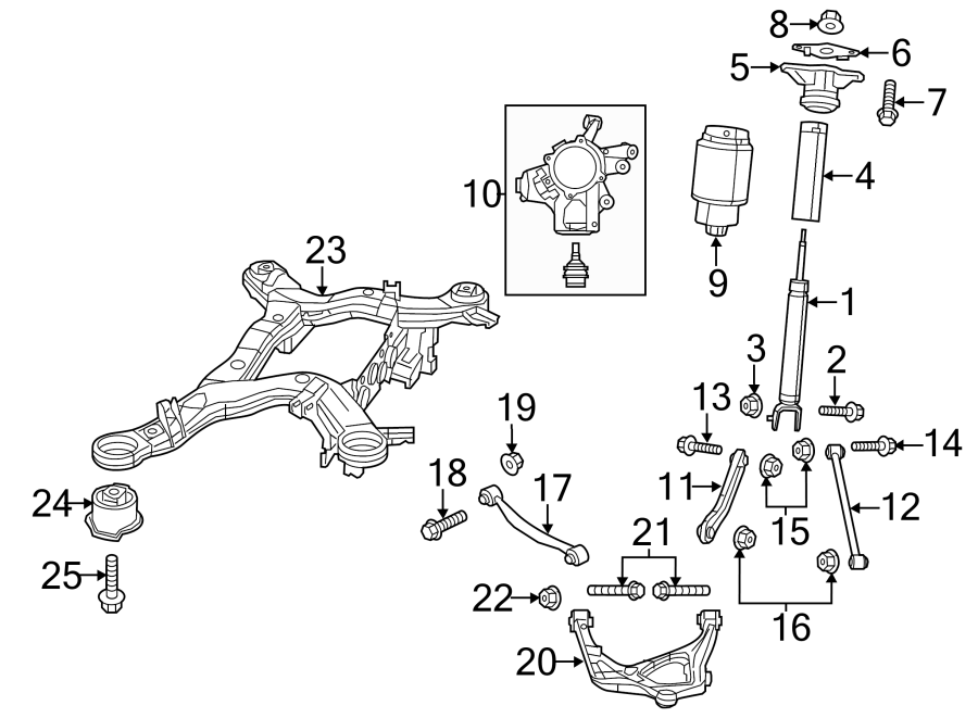
Jeep Grand Cherokee Rear Suspension Diagram
The rear suspension of your Jeep Grand Cherokee is a complex system working tirelessly to provide a comfortable ride, maintain traction, and ensure vehicle stability. Understanding its intricacies is invaluable, whether you're planning routine maintenance, diagnosing a problem, considering modifications, or simply want to deepen your automotive knowledge. This article will dissect the rear suspension diagram of a typical Grand Cherokee, empowering you to navigate its components and functions with confidence.
Purpose of the Rear Suspension Diagram
A rear suspension diagram isn't just a pretty picture; it's a vital tool. Its primary purposes include:
- Diagnosis and Repair: When experiencing issues like a sagging rear end, unusual noises, or poor handling, the diagram helps pinpoint the problematic component.
- Maintenance: It guides you through regular maintenance tasks such as inspecting bushings, checking shock absorbers, and lubricating moving parts.
- Modification and Upgrades: If you're planning to lift your Grand Cherokee, install aftermarket shocks, or upgrade sway bars, the diagram provides crucial information about component locations and compatibility.
- Understanding System Operation: Even if you're not actively working on your vehicle, understanding the diagram provides a clearer picture of how the rear suspension functions.
Key Specs and Main Parts
While specific designs may vary slightly across different Grand Cherokee generations (e.g., WJ, WK, WK2, WL), the fundamental principles remain the same. Common elements include:
Main Components:
- Coil Springs: (or Leaf Springs on older models): These provide the primary suspension support, absorbing bumps and maintaining ride height. The spring rate, measured in pounds per inch (lbs/in), dictates how much force is required to compress the spring one inch. A higher spring rate means a stiffer ride.
- Shock Absorbers (Dampers): These control the rate of spring compression and rebound, preventing excessive bouncing and oscillations. They typically contain hydraulic fluid that is forced through small orifices, creating resistance to movement. Adjustable shocks allow you to fine-tune the damping characteristics.
- Upper and Lower Control Arms (A-Arms or Trailing Arms): These arms connect the rear axle or hub to the vehicle's frame. They control wheel movement and maintain proper suspension geometry. The arms are connected to the frame and axle/hub using bushings, which are typically made of rubber or polyurethane.
- Rear Axle (or Independent Rear Suspension Components): In solid axle setups, the axle connects both rear wheels. In independent rear suspension (IRS) systems, each wheel has its own suspension components.
- Sway Bar (Stabilizer Bar): This torsion bar connects the left and right sides of the suspension, reducing body roll during cornering. It twists when one side of the suspension moves more than the other, providing resistance to prevent excessive lean.
- Track Bar (Panhard Rod): Used in solid axle setups, the track bar locates the axle laterally (side-to-side) under the vehicle. It prevents the axle from shifting sideways.
- Bushings: These flexible components connect various suspension parts, absorbing vibrations and allowing for movement.
- Bump Stops: These prevent the suspension from bottoming out, protecting the vehicle's frame and suspension components from damage.
- Wheel Hub/Bearing Assembly: Supports the wheel and allows it to rotate freely.
Key Specs to Consider:
- Ride Height: The distance between the ground and a specific point on the vehicle's frame.
- Wheel Alignment Angles: Caster, camber, and toe angles affect tire wear and handling.
- Spring Rate: As mentioned earlier, this affects ride stiffness.
- Shock Absorber Damping Force: This influences ride comfort and handling.
Symbols on the Rear Suspension Diagram
Diagrams use standardized symbols to represent different components. Here's a breakdown of common conventions:
- Solid Lines: Typically represent solid components like control arms, axles, and frame members.
- Dashed Lines: May indicate hidden components or lines of force.
- Circles: Often represent bushings or pivot points.
- Hatch Marks: Indicate cross-sections or areas of detail.
- Arrows: Show the direction of movement or force.
- Color Coding: Some diagrams use colors to differentiate between different systems or components. For example, blue might represent hydraulic lines, while red might represent electrical wiring (related to electronic shocks).
- Abbreviations: Common abbreviations include "UBJ" (Upper Ball Joint), "LBJ" (Lower Ball Joint), "S/A" (Shock Absorber), and "S/B" (Sway Bar).
How It Works
The rear suspension works by absorbing energy from road imperfections and maintaining consistent contact between the tires and the road surface. Let's break it down:
- Impact Absorption: When a wheel encounters a bump, the coil spring (or leaf spring) compresses, absorbing the initial shock.
- Damping: The shock absorber then controls the spring's compression and rebound, preventing it from oscillating excessively. This ensures a smooth and controlled ride.
- Wheel Control: The control arms (A-arms or trailing arms) guide the wheel's movement, keeping it aligned properly and preventing unwanted lateral or longitudinal movement. Bushings in the control arms allow for controlled articulation while absorbing vibrations.
- Lateral Stability: The sway bar (if equipped) reduces body roll during cornering by transferring force between the left and right sides of the suspension. The track bar (on solid axle vehicles) prevents the axle from shifting sideways.
In an independent rear suspension (IRS) system, each wheel functions independently. This allows for greater wheel articulation and improved handling, particularly on uneven surfaces. However, IRS systems are typically more complex and expensive than solid axle setups.
Real-World Use: Basic Troubleshooting Tips
Here are some common problems and how the diagram can help you troubleshoot them:
- Sagging Rear End: Could indicate worn coil springs or air suspension problems (if equipped). The diagram will show you the location and type of springs used.
- Clunking Noises: Often caused by worn bushings, loose bolts, or damaged shocks. The diagram helps you identify the location of each bushing and shock absorber for inspection.
- Poor Handling: Could be due to worn shocks, damaged control arms, or misaligned suspension. The diagram allows you to verify the integrity of each component and check alignment specifications.
- Uneven Tire Wear: Can result from misaligned suspension or worn suspension components. The diagram can help you identify components that may be contributing to the problem.
When troubleshooting, always start with a visual inspection. Look for signs of damage, wear, or leakage. Use the diagram to guide your inspection and ensure that you are checking all relevant components.
Safety Considerations
Working on suspension systems can be dangerous. Here are some critical safety precautions:
- Spring Compression: Coil springs store enormous energy. Never attempt to disassemble a suspension without using a properly rated spring compressor. Improper use can result in serious injury or death.
- Vehicle Support: Always use jack stands to support the vehicle before working underneath it. Never rely solely on a jack.
- Torque Specifications: Always torque bolts to the manufacturer's specified torque. Overtightening can damage components, while undertightening can lead to failure.
- Brake Lines: Be careful not to damage brake lines when working on the suspension. Damage to brake lines can result in loss of braking ability.
- Air Suspension: If your Grand Cherokee has air suspension, be sure to depressurize the system before working on it.
The rear suspension system is under considerable stress. Components can be corroded or seized, making disassembly difficult. Use penetrating oil and appropriate tools to avoid damaging parts or injuring yourself.
We have the rear suspension diagram available for download. It contains a detailed view of all parts and connections in the rear suspension system. Download the diagram for a comprehensive guide to your Jeep Grand Cherokee's rear suspension and use it as a valuable resource for repairs, maintenance, and upgrades.